ENGLISH
17 / 35
0006081444_201610
•
Progressively adjust the motor rotation speed and therefore
the air flow by pressing the in or – keys, checking with
appropriate instruments that the combustion is correct (C02
max= 10%, O2 min=3%, CO max=0,1%).
•
Having finished the air and gas flow adjustment, check the
actual gas flow rate by reading the meter.
•
Avoid keeping the burner running if the heating capacity is
greater than the maximum amount allowed for the boiler, to
avoid damaging it.
FIRST STAGE POWER REGULATION
Having finished regulating the burner in the second stage, put the
burner into the first stage without varying the regulation of the gas
valve already undertaken in the previous point.
With the aid of appropriate instruments adjust air and gas flow
according to the procedures described below:
•
To adjust the air flow rate proceed with the setting of the servo
control air adjustment cam in first stage, until the desired gas
flow rate is obtained, as the rotation of the gas throttle is derived
from the rotation of the air damper.
•
To adjust the air flow rate, vary the rotation speed of the fan motor
in first stage then proceed with the adjustment of the inverter V1
parameter (see chapter “FREQUENCY CONVERTER”).
•
Progressively adjust the motor rotation speed and therefore
the air flow by pressing the in or – keys, checking with
appropriate instruments that the combustion is correct (C02
max= 10%, O2 min=3%, CO max=0,1%).
•
Having finished the air and gas flow adjustment, check the
actual gas flow rate in first stage by reading the meter.
Ignition of the burner takes place with the air damper and gas
throttle adjusted for first stage operation.
Once adjustment of the first stage has been carried out the burner
needs to be switched off with verification that the ignition is not
noisy.
In the event of pulsations during ignition, it is possible to "adjust"
the air flow rate for ignition proceeding with the adjustment
of the inverter Vs parameter (see chapter “FREQUENCY
CONVERTER”).
It is often advisable to set Vs at a slightly higher value than V1.
ADJUSTING THE AIR PRESSURE SWITCH.
Put the burner into first stage operation and increase the air
pressure switch setting until the burner goes into lock-out.
Adjust the setting of the pressure switch to a level slightly below
the actual air pressure detected in first stage operation.
Release the burner and check that it starts up correctly.
SECOND STAGE AIR PRESSURE SWITCH
Some burners are equipped with two air pressure switches which
take the pressure signal in the same point inside the fan.
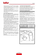
The pressure switch (1) (see diagram) carries out the function of
safety device envisaged by standard EN 676.
The pressure switch for second stage air pressure control (2)
allows surveillance of the proper operation of the burner in the
second stage of power.
For example, if due to a faulty inverter, when passing from first to
second stage, the motor does not reach V2 speed (see chapter:
“FREQUENCY CONVERTER”), necessary to guarantee the
supply of the correct combustion air flow rate, the pressure switch
for second stage air pressure control detects pressure lower than
that set and locks out the burner.
When the burner does not operate in second stage, the signal
from the pressure switch (2) is ignored and the burner control is
assigned to the pressure switch (1) as envisaged by the standard.
Air pressure switch adjustment
scale (1):
0.4 ÷ 3 mbar
Second stage air control pressure
switch adjustment scale (2):
2.5 ÷ 50 mbar
Содержание TBG 45 PV
Страница 2: ......
Страница 36: ...ITALIANO 34 35 0006081444_201610 SCHEMI ELETTRICI...
Страница 71: ...ENGLISH 34 35 0006081444_201610 WIRING DIAGRAMS...
Страница 73: ......

