16 / 36
0006081062_200
904
E
N
G
L
I
S
H
Control box or
programmer
Safety time
s
Preventila
-
tion time
s
Pre-
ignition
s
Post-
ignition
s
Time betwe
-
en opening of
pilot valves and
opening of main
valves
s
Cut out of pilot
flame after opening
of main valves
s
Time between ope
-
ning1st flame valve
and 2nd flame
valve
s
LFL 1.333
3
31,5
6
3
12
3
12
DESCRIPTION OF WORKING
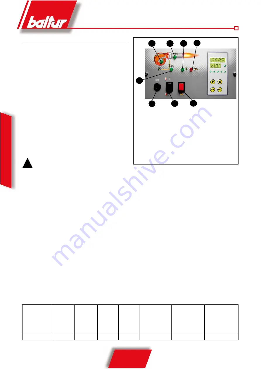
Closing switch 1, if the thermostats are closed, the voltage reaches
the command and control equipment (switching on of LED 2) which
starts it working. The fan motor is thus switched on (LED 3) to carry
out the preventilation of the combustion chamber, at the same time
the air damper control servo motor moves to the opening position
corresponding to the maximum regulated power.
At the end of the preventilation stage the air damper has to be
returned to the ignition flame position. If the pressure control switch
for the ventilation air detects sufficient pressure, the ignition tran
-
sformer goes on (LED 4) and, after two seconds, the main gas and
safety valves open (LED 5)
Note that:
a) The main valve has a device for the proportional adjustment of
the air to gas ratio.
b) The safety valve is an ON/OFF type.
c) The air damper is activated by an electric servo motor (see
0002933220 to 200Lx at 390Lx and 0002933490 for 540Lx)
, re-
member that when the burner is stopped by
the thermostat, the gate damper
is brought back by the servo motor to its closed position.
!
The gas supply at the ignition flame position must ge
-
nerally be greater than the minimum modulation capa
-
city. The ignition flame position can be adjusted with
the air damper control servo motor. (see
0002933220
to 200Lx at 390Lx and 0002933490 for 540Lx).
The presence of the flame, detected by the control device
itself, permits the continuance and completion of the igni
-
tion stage with the switching off of the ignition transformer.
Subsequently the servo motor progressively opens the air
damper and the pneumatic valve allows the gas supply to
increase to its set maximum.
If there is no flame, the control box stops in its “safety lock-
out” (LED 7) within 3 seconds from the opening of the main
valve. In the case of safety lock-out the valves immediately
close again. To release the control box from its safety posi
-
tion press button 8 on the display panel.
DESCRIPTION OF MODULATION WORKING
When the burner is running at minimum capacity, if the modula
-
tion probe allows, (adjusted to a temperature or pressure value
greater than that in the boiler) the air adjustment servo motor
starts to turn causing gradual increase in combustion air sup
-
ply and, consequently also of gas, up to the maximum supply
for which the burner has been set. The increase in the fan air
pressure is detected by the proportional gas valve sensor which
gradually adjusts gas supply to the change in air pressure.
The burner stays at maximum delivery until the temperature or
pressure reaches a level high enough to cause the modulation pro
-
be to turn the air adjustment servo motor in the opposite direction.
The backward rotation and consequent reduction in gas and air
supply happens at brief time intervals. With this manoeuvre the
modulation system seeks to balance the quantity of heat supplied
to the boiler with that which the boiler itself provides. The modu
-
lation probe applied to the boiler detects changes in demand and
automatically adjusts the supply of fuel and of combustion air,
switching on the servo motor with an increased or decreased rota
-
tion. If, even with fuel supply at minimum, the limit value is reached
(temperature or pressure) for which the device is set for complete
stop, (through thermostat or pressure switch) the burner is stopped
by the device.
By lowering the temperature or pressure again below the burner
stop device-triggering figure it is switched on again in accordance
with the program described in the previous paragraph.
1
2
3
4
6
8
7
5
1 Main ON-OFF switch
2 Live voltage light
3 Fan working light
4 Transformer on light
5 Gas valves working indicator light
6 Safety fuses
7 Control box lock-out light
8 Control box release button
Содержание BGN 200 LX
Страница 2: ......
Страница 4: ...0006081062_200904...
Страница 8: ...36 36 0006081062_200904 I T A L I A N O...
Страница 30: ...22 36 0006081062_200904 E N G L I S H...
Страница 31: ...23 36 0006081062_200904 E N G L I S H CAMS REGULATION SERVONMOTOR SQM 10 20 FOR BGN LX N 0002933490...
Страница 37: ...29 36 0006081062_200904 E N G L I S H Pe Gas inlet pressure...
Страница 39: ...31 36 0006081062_200904 E N G L I S H...
Страница 43: ...36 36 0006081062_200904 E S P A O L...
Страница 44: ...149 162 0006081062_200904...
Страница 45: ...150 162 0006081062_200904...
Страница 46: ...151 162 0006081062_200904...
Страница 47: ...152 162 0006081062_200904...
Страница 48: ...153 162 0006081062_200904...
Страница 49: ...154 162 0006081062_200904...
Страница 50: ...155 162 0006081062_200904...
Страница 51: ...156 162 0006081062_200904...
Страница 52: ...157 162 0006081062_200904...
Страница 53: ...158 162 0006081062_200904...


