background image

10 / 42

0006080764 _201312

00

02

90

11

20

ENGLISH

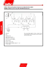
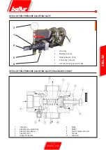
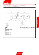
SUPPLY HYDRAULIC DRAWING FOR LIQUID FUEL BURNERS WITH MAXIMUM 

NOMINAL VISCOSITY (5°E AT 50°C) WITH PRESSURE REGULATOR

The oil recovery tanks (diameter ~ 150 mm - height ~ 400 mm) 

must be installed as close as possible to the burner at least 0.5 

m above the burner pump.

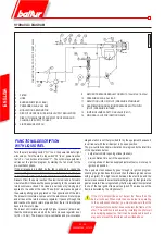
1 - Main tank
2 - Filter
3 - Circulation pump
4 - Water and system outlet
5 - Air/gas outlet - normally closed
6 - Fuel recovery tank and degasser
7 - Non-return valve
8 - By-pass (normally closed)
9 - Pressure regulator adjustable between 0.2 - 1 bar
10 - Pressure gauge

TO BURNER

TO BURNER

TO BURNER

Содержание 66875410

Страница 1: ...VE MODULATING TWO STAGE MIXED GAS DIESEL BURNERS Manuale istruzioni per l uso UK Instruction manual BRUCIATORI MISTI GAS GASOLIO A DUE STADI PROGRESSIVI MODULANTI ISTRUZIONI ORIGINALI IT ORIGINALINSTR...

Страница 2: ......

Страница 3: ...eseguiti solo da personale qualificato L alimentazione elettrica dell impianto deve essere disinserita prima di iniziare i lavori Se i lavori non sono eseguiti correttamente si rischiano incidenti pe...

Страница 4: ...sia stato rilevato difetto di conformit resteranno di propriet della Baltur S p A e dovranno essere recapitati al magazzino ricambi Baltur S p A La sostituzione di parti in garanzia rinnova la durata...

Страница 5: ...ispettano i requisiti minimi imposti dalle Direttive Europee 2009 142 CE D A G 2004 108 CE C E M 2006 95 CE D B T 2006 42 CE D M e sono conformi alle Norme Europee EN 676 2003 A2 2008 gas e misti lato...

Страница 6: ...l libretto accompagni l apparecchio in modo che possa essere consultato dal nuovo proprietario e o dall installatore Per tutti gli apparecchi con optionals o kit compresi quelli elettrici si dovranno...

Страница 7: ...l combustibile onde rimuovere eventuali residui che potrebbero compromettere il buon funzionamento del bruciatore Per la prima messa in funzione dell apparecchio far effettuare da personale profession...

Страница 8: ...di potenza Possibilit di funzionamento a modulazione di potenza tramite montaggio sul quadro di comando del regolatore elettronico di modulazione da ordinare a parte assieme al kit di modulazione spec...

Страница 9: ...2 ITALIANO Mod A A1 A2 B B1 B2 B3 B4 B5 B6 C D E GI mist 1000 DSPGM 1465 800 665 1260 855 405 450 575 175 163 2350 440 480 Mod F G G1 L M N P Q R S GI mist 1000 DSPGM 685 DN80 Rp1 2 630 M16 495 740 19...

Страница 10: ...uciatore serie GI 1000 modulante con campo di mo dulazione da 1 4 L adattamento al momentaneo fabbisogno termico si ottiene mediante un servomotore che regola in ma niera combinata la quantit di aria...

Страница 11: ...ermeticit della tubazione del gas deve essere verificata prima del collaudo del bruciatore IMPIANTO DI ALIMENTAZIONE CON COMBUSTIBILE LIQUIDO La pompa del bruciatore deve ricevere il combustibile da u...

Страница 12: ...ezza 400 mm devono essere installati il pi vicino possibile al bruciatore ad una quota superiore di almeno 0 5 m rispetto alla pompa dello stesso 1 Cisterna principale 2 Filtro 3 Pompa di circolazione...

Страница 13: ...Filtro 3 Recupero combustibile e degasatore 4 Valvola unidirezionale 5 Filtro 6 By pass normalmente chiuso 7 Valvola di non ritorno 8 By pass normalmente chiuso AL BRUCIATORE AL BRUCIATORE AL BRUCIAT...

Страница 14: ...ffettua con serranda aria nella posizione aperta Il tempo di preventilazione e precircolazione risulta pertanto dalla somma dei tempi delle seguenti manovre corsa di apertura del servomotore dell erog...

Страница 15: ...ulle viti che variano il profilo del disco di comando della regolazione dell aria di combustione L erogazione del combustibile e contemporaneamente dell aria comburente aumenta fino al valore massimo...

Страница 16: ...E DI APERTURA 10 REGOLATORE PRESSIONE RITORNO MIN 10 12 BAR MAX 18 20 BAR 11 SERVOMOTORE DI MODULAZIONE 12 DISCO COMANDO REGOLAZIONE ARIA COMBUSTIBILE 13 SERRANDE ARIA 14 TUBO FLESSIBILE 15 PILOTA DI...

Страница 17: ...ER CIRCUITO AUSILIARIO 1 Corpo valvola 2 Tappo di sostegno vite regolazione 3 Dado di bloccaggio vite di regolazione 4 Vite di regolazione 5 Bussola di centraggio molla 6 Molla 7 Otturatore 8 Attacco...

Страница 18: ...torno combustibile N B Per un buon funzionamento dell ugello indispensabile che il ritorno dello stesso non sia mai completamente chiuso Questa condizione deve essere realizzata operando opportunament...

Страница 19: ...la pressione di ritorno Aprire ora tutte le saracinesche ed eventuali altri organi di intercettazione posti sulle tubazioni del gasolio Portarel interruttore postosulquadrodicomando nellaposizione O a...

Страница 20: ...sopra specificato Precisiamo che la massima erogazione si ottiene quando la pressione di ritorno di circa 2 3 bar inferiore alla pressione di mandata normalmente 20 22 bar Per un corretto rapporto ari...

Страница 21: ...to pilota si disinserisce dopo l apertura delle valvole principali Il servomotore di modulazione viene inserito dopo l apertura delle valvole principali e se il termostato o pressostato modulante lo c...

Страница 22: ...DI REGOLAZIONE PER APERTURA E CHIU SURAARIAALLA TESTA 12 VALVOLA GAS DI SICUREZZA FIAMMA D ACCENSIONE PI LOTA 13 VALVOLA GAS DI LAVORO CON REGOLATORE DI PRESSIO NE 14 VALVOLA GAS SICUREZZA 15 VALVOLA...

Страница 23: ...tare gli interruttori della modulazione in posizione MIN minimo e MAN manuale L apparecchiatura di comando riceve cos tensione ed il programmatore determina l inserzione del bruciatore come descritto...

Страница 24: ...ienza del rilevatore di fiamma fotocellula UV sfilando la stessa dalla sede sul bruciatore e verificare l arresto in blocco Verificare l efficienza dei termostati o pressostati di caldaia l intervento...

Страница 25: ...use Grande apertura passaggio aria Testa di combustione REGOLAZIONE CORRETTA Ingresso aria di combustione serrande sensibilmente aperte Passaggio aria relativamente chiuso Attenzione Evitare la chiusu...

Страница 26: ...si chiude il contatto NO normalmente aperto previsto per essere chiuso in lavoro pressione aria insufficiente l apparecchiatura esegue il suo ciclo ma non si inserisce il trasformatore d accensione e...

Страница 27: ...i di combustione Sono dotate di Approvazione M I e CE per EN 161 REGOLAZIONE Per modelli VE 4000B1 vedi fig 1 Regolazione della portata Togliere il coperchio sulla parte superiore della bobina Inserir...

Страница 28: ...are il pressostato di minima aumentando il valore di taratura fino a che il bruciatore si spegne leggere il valore sulla ghiera di regolazione e regolare la stessa diminuita di 5 mbar Con bruciatore s...

Страница 29: ...r E nel caso di controllo di tenuta pu supportare una depressione fino a 200 mbar Le carcasse del servomotore e del regolatore di pressione sono in alluminio pressofuso Descrizione del funzionamento v...

Страница 30: ...i standard offrendo un elevato livello di sicurezza aggiuntiva Il test del rivelatore di fiamma ed il test di falsa fiamma ripar tono immediatamente dopo il tempo di post combustione tollerato Se le v...

Страница 31: ...zione MIN della serranda aria M Motore ventilatore o bruciatore NTC Resistore NTC QRA Sonda UV R Termostato o pressostato RV Valvola del combustibile a regolazione continua S Fusibile SA Servomotore s...

Страница 32: ...a la fine di t4 ed il consenso al regolatore di potenza o alla valvola sul morsetto 20 18 t6 Tempo di post ventilazione con M2 3 t7 Intervallo tra consenso all avviamento e tensione al morsetto 7 rita...

Страница 33: ...applicativo Programma di comando in caso di interruzione e indicazione della posizione di interruzione In linea di principio in caso di interruzione di qualsiasi natura l afflusso di combustibile imm...

Страница 34: ...tenuta impedisce l avviamento del bruciatore fermandosi in blocco spia rossa accesa Se la verifica della seconda fase favorevole l apparecchio LDU 11 chiude il circuito interno di comando tra i morset...

Страница 35: ...lsante di sblocco GP pressostato esterno della pressione del gas di rete HR rel ausiliario con i contatti hr L1 lampada di segnalazione anomalia dell apparecchio SK interruttore di linea I XI contatti...

Страница 36: ...lettrodo accensione 5 Svitare dado per raccordo Woss per estrarre tubo pilota 6 Sfilare perno cerniera 7 Estrarre vite superiore cerniera e aprire bruciatore 8 Estrarre vite di bloccaggio gruppo polve...

Страница 37: ...35 42 0006080764 _201312 ITALIANO schema elettrico...

Страница 38: ...36 42 0006080764 _201312 ITALIANO...

Страница 39: ...37 42 0006080764 _201312 ITALIANO...

Страница 40: ...38 42 0006080764 _201312 ITALIANO...

Страница 41: ...39 42 0006080764 _201312 ITALIANO...

Страница 42: ...40 42 0006080764 _201312 ITALIANO...

Страница 43: ...41 42 0006080764 _201312 ITALIANO RAMPA PILOTA RAMPA PRINCIPALE...

Страница 44: ...P M PRESSOSTATO DI MASSIMA PA PRESSOSTATO ARIA Pm PRESSOSTATO DI MINIMA PmP PRESSOSTATO DI MINIMA RAMPA PILOTA PMP PRESSOSTATO DI MASSIMA RAMPA PILOTA Q1 SEZIONATORE GENERALE BLOCCO PORTA S1 INTERRUTT...

Страница 45: ...d personnel The system power supply must be disconnected before starting any works If the works are not carried out correctly it is possible to cause dangerous accidents The following symbols have bee...

Страница 46: ...2 42 0006080764 _201312 ENGLISH...

Страница 47: ...low NOx emissions respect the minimal regulation of the European Directives 2009 142 EC G A D 2004 108 EC E M C 2006 95 EC L V D 2006 42 EC M D andhavebeendesignedandtestedinaccordancewiththeEuropeanS...

Страница 48: ...ves and leaves the equipment make sure that the booklet always goes with the equipment so it can be consulted by the new owner and or installer For all equipment with optionals or kits including elect...

Страница 49: ...T OIL OR OTHER FUEL SUPPLIES General warning notes Installation of the burner must be carried out by qualified technicians and in compliance with current law and regulations since incorrect installati...

Страница 50: ...low rate regulation by means of electric servomotor with pause closure of shutter to prevent any heat dispersion to chimney Valve seal control according to European Standard EN676 Preset for fuel auto...

Страница 51: ...552 ENGLISH OVERALL DIMENSIONS Mod A A1 A2 B B1 B2 B3 B4 B5 B6 C D E GI mist 1000 DSPGM 1465 800 665 1260 855 405 450 575 175 163 2350 440 480 Mod F G G1 L M N P Q CLK S GI mist 1000 DSPGM 685 DN80 Rp...

Страница 52: ...the momentary thermal requirement is done using a servomotor that regulates the quantity of comburent air and fuel in a combined manner upon the command of the probe in the boiler The burner is fitte...

Страница 53: ...e The tightness of the pipe fitting should be checked before switching on the burner Liquid FUEL SUPPLY SYSTEM The burner pump should receive fuel from a feed circuit which has an ancillary pump and i...

Страница 54: ...er 150 mm height 400 mm must be installed as close as possible to the burner at least 0 5 m above the burner pump 1 Main tank 2 Filter 3 Circulation pump 4 Water and system outlet 5 Air gas outlet nor...

Страница 55: ...E at 50 C 1 Main tank 2 Filter 3 Fuel and degasser recovery 4 Non return valve 5 Filter 6 By pass normally closed 7 Non return valve 8 By pass normally closed The oil recovery tanks diameter 150 mm he...

Страница 56: ...ation and pre circulation time is given by the total time of the operations below output servomotor opening stroke fuel air pre ventilation time set in the equipment closing stroke of fuel air supply...

Страница 57: ...ry the profile of the control disc that regulates the combustion air Fuel flow and at the same time combustion air flow increase up to maximum pressure fuel pressure at return pressure regulator of ab...

Страница 58: ...NG SPRINGS 9 OPENING ELECTROMAGNET 10 RETURN PRESSURE REGULATOR MIN 10 12 BAR MAX 18 20 BAR 11 MODULATION SERVOMOTOR 12 AIR FUEL REGULATION CONTROL DISC 13 AIR GATES 14 HOSE 15 IGNITION PILOT 16 MAIN...

Страница 59: ...VALVE FOR AUXILIARY CIRCUIT 1 Valve body 2 Adjusting screw support plug 3 Adjusting screw stop nut 4 Adjusting screw 5 Spring centring bush 6 Spring 7 Shutter 8 Pressure gauge connection 9 Fuel inlet...

Страница 60: ...e burner for the first time In practice when the nozzle is operating at the maximum desired output the difference between delivery to nozzle pump pressure and return from nozzle pressure at the return...

Страница 61: ...the main line to invert the rotation sense Start the burner pump by manually pressing the relevant remote control switch until the pump pressure gauge detects a slight pressure The presence of low pre...

Страница 62: ...3 at maximum flow It is inadvisable to exceed a CO2 value of 13 so as to prevent operation with a rather limited excess of air which could lead to a significant increase in smoke opacity due to unavoi...

Страница 63: ...at the minimum setting The pilot circuit cuts out after the main valves open The modulator servo motor cuts in after the main valves open and on a consent signal from the modulating thermostat or pre...

Страница 64: ...1 DISK WITH ADJUSTMENT SCREWS FOR OPENING AND CLOSING AIR SUPPLY REGULATION TO HEAD 12 IGNITION FLAME SAFETY GAS VALVE PILOT 13 OPERATING GAS VALVE WITH PRESSURE REGULATOR 14 SAFETY GAS VALVE 15 IGNIT...

Страница 65: ...d position without pressure measurement to the closed position with pressure measurement If the pressure switch does not detect sufficient pressure and does not change status neither the ignition tran...

Страница 66: ...ol devices as described in the chapter Operation description The shut down position is a safety position automatically taken up by the burner when a particular part of the burner or the system is inef...

Страница 67: ...TMENT DIAGRAM WRONG ADJUSTMENT Combustion air inlet gates very closed Air passageway wide open Combustion head CORRECT ADJUSTMENT Combustion air inlet gates considerably open Air passage relatively cl...

Страница 68: ...rmally open as it should be during working this may be due to insufficient air pressure the equipment carries out its working cycle but does not switchontheignitiontransformeranddoesnotopenthegaspilot...

Страница 69: ...rovided with M I and CE Approval for EN 161 ADJUSTMENT For models VE 4000B1 see fig 1 Flow rate adjustment Remove the cover from the upper part of the coil Insert a hexagon wrench in the upper central...

Страница 70: ...livery regulate the pressure switch for minimum pressure by increasing the regulation value until the burner shuts down read the value on the regulation ferrule and set it to a value diminished by 5 m...

Страница 71: ...is 700 mbar Where there is seal control a depression of up to 200 mbar can be withstood The servomotor and pressure regulator casings are made out of die cast aluminium Operation of valve with pressur...

Страница 72: ...close immediately after the regulation stop a shutdown in lock condition is triggered at the end of the allowed post combustion time The tests finish only at the end of the pre ventilation time of th...

Страница 73: ...y switch contact for air gate MIN position M Fan or burner motor NTC NTC Resistor QRA UV probe R Thermostat or pressure switch RV Fuel valve with continuous regulation S Fuse SA Air gate servomotor SB...

Страница 74: ...the consensus to the power regulator or the valve on terminal 20 18 t6 Post ventilation time with M2 3 t7 Time between consensus upon start up and the voltage to terminal 7 start delay for fan motor...

Страница 75: ...Electromagnetic emissions must be verified during use Control programme in case of stopping and indication of stop position As a rule in the event of any kind of stop the fuel flow is immediately cut...

Страница 76: ...n shutdown state red light on If the second phase check is successful the LDU 11 device closes the internal circuit across terminals 3 and 6 terminal 3 contact ar2 external U bolt of terminals 4 and 5...

Страница 77: ...re switch leak test EK reset key GP external pressure switch of system gas pressure HR reset relay with hr contacts L1 lamp signalling device faults SK line switch I XI programmer cam contact N 000293...

Страница 78: ...trode cable 5 Unscrew the Woss coupling nut to take out the pilot tube 6 Take out the hinge pivot 7 Take out the hinge upper screw and open the burner 8 Take out the blocking screw of the atomising gr...

Страница 79: ...35 42 0006080764 _201312 ENGLISH Wiring diagram...

Страница 80: ...36 42 0006080764 _201312 ENGLISH...

Страница 81: ...37 42 0006080764 _201312 ENGLISH...

Страница 82: ...38 42 0006080764 _201312 ENGLISH...

Страница 83: ...39 42 0006080764 _201312 ENGLISH...

Страница 84: ...40 42 0006080764 _201312 ENGLISH...

Страница 85: ...41 42 0006080764 _201312 ENGLISH PILOT TRAIN MAIN TRAIN...

Страница 86: ...OR P M MAXIMUM PRESSURE SWITCH PA AIR PRESSURE SWITCH Pm GAS MIN PRESSURE SWITCH PmP PILOT TRAIN MINIMUM PRESSURE SWITCH PMP PILOT TRAIN MAXIMUM PRESSURE SWITCH Q1 MAIN DOOR BLOCK DISCONNECTOR S1 STAR...

Страница 87: ......
Страница 88: ...info baltur it Il presente catalogo riveste carattere puramente indicativo La casa pertanto si riserva ogni possibilit di modifica dei dati tecnici e quant altro in esso riportato Technical data in th...

Отзывы: