


4
PRODUCT
DESCRIPTION
18
www. matrix-vision.com
BVS SC-_1280Z00-30-0-0
SMART
CAMERA
Fieldbus
www.balluff.com
The power plug connector supplies the
SMARTCAMERA
with the supply voltage and
offers two I/O-24V switching signals (I/O 0 & I/O 1) for the connection with sensors, ac-
tuators or PLC.
These two inputs and outputs feature a push-pull output stage. This allows using the
output signal for PNP logic as well as NPN logic. The input stage always features PNP
logic.
I/O 0 & I/O 1 (power plug connectors)
Operation as input
Voltage
Signal 0
0…5 V
< 2 mA
Signal 1
11…30 V
2…5 mA
Delay
< 160 μs
Operation as output
Voltage
Signal 0
0 V (+V
D
)
100 mA max.
Signal 1
24 V (V
DC
– V
D
)
100 mA max.
Voltage drop V
D
< 2 V
Delay
< 10 μs
See also the guideline on digital inputs, EN 61131-2, Type 3.
Below are examples how inputs and outputs must be connected to obtain input and
output function.
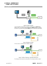
Input connection
If I/O 0 is configured as input, it is sinking and can be connected directly with the PNP
output of a sensor, a PLC. A 1 signal is being detected if the input is connected with the
supply voltage. A 0 signal is being detected if the input is set to ground or is not connect-
ed.
If an NPN device is to be connected to the input, then an external level converter must
be connected upstream.
Figure 4 Input connection
4.4.2 Power
Содержание SMARTCAMERA
Страница 1: ...BVS SC _1280Z00 30 0 0 SMARTCAMERA Fieldbus User s manual ...
Страница 2: ...www balluff com ...


