background image

  28

0711

  30

0762

  32

0813

  36

0914

  40

1016

  inches

mm

  15

0381

  16

0407

  18

0457

  20

0508

  22

0560

  24

0610

  26

0661

Rugged,

Compact

Rod Style

Compact,

bolt-in

Rod Style

Rod Style

Explosion-proof

Rod Style

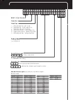
Balluff - Linear Transducer

Generation  5

Output Type

Supply Voltage

1 = 24 Vdc ±20%
2 = ±15 Vdc ±2%

Normal Stroke Length

Housing Type

P = Standard Profile Housing

Connection Type

S     3    2

K    A     0     5

= 8-pin quick disconnect metal connector

= Cable out (5m standard; specify length in meters)

Differential start/stop with tri-state
Differential stop - leading edge active
Differential pulse-width modulated
Differential start/stop - leading edge active
Single ended start/stop - leading edge active
Differential start/stop - trailing edge active

I
K
L
M
N
P

=
=
=
=
=
=

 K   A    0   5

 0         3           0         5

= 305mm active stroke

 1    2     3    4     5     6     7     8     9  10   11   12  13   14   15  16   17  18   19   20   21  22


B    T    L    -    5     -    P     1    -   M    0     3    0     5    -    P    -     S    3    2

Standard Stroke Lengths 

(consult factory for additional lengths)

  inches

mm

  148

3759

  156

3962

Electrical Stroke

 inches

mm

  2

0051

  3

0077

  4

0102

  5

0127

  6

0152

  7

0178

  8

0203

  9

0230

 10

0254

 11

0280

 12

0305

 13

0330

inches

mm

  42

1067

  48

1220

  50

1270

  60

1524

  70

1778

  80

2032

  90

2286

  100

2540

  110

2794

  120

3048

  130

3302

  142

3606

Содержание BTL5-P

Страница 1: ...Sensors Worldwide BTL5 P I K L M_ M U_ _ _ _ P S 32 KA_ _ Micropulse Linear Transducer Digital Output Profile Housing Technical Description User s Guide...

Страница 2: ......

Страница 3: ...stop with tri state Differential stop leading edge active Differential pulse width modulated Differential start stop leading edge active Single ended start stop leading edge active Differential start...

Страница 4: ...stallation 3 3 2 Floating magnets 4 3 3 Captive magnets 5 4 Wiring 6 5 Startup 7 5 1 Check connections 7 5 2 Turning on the system 7 5 3 Check output values 7 5 4 Check functionality 7 5 5 Fault condi...

Страница 5: ...provides an unreliable signal but which may be entered The electrical connection between the transducer the processor controller and the power supply is via a cable which depending on the version is...

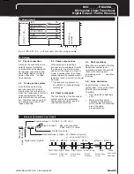
Страница 6: ...is attached to the moving member of the machine using non magnetizable screws brass aluminum To ensure the accuracy of the transducer system the moving member must carry the magnet on a track paralle...

Страница 7: ...5 stud using 2 nuts Max angle offset Max parallel offset BTL5 M 2814 1S X 48 5 Y 57 BTL5 N 2814 1S X 51 Y 59 5 3 3 Captive magnets Lateral forces are to be avoided when using captive magnets Figs 3 6...

Страница 8: ...d power supply avoid proximity to high voltage lines to prevent noise coupling Especially critical is inductive noise caused by AC harmonics e g from phase control devices against which the cable shie...

Страница 9: ...the replacement or repair are found a correction should be made Transducers are subject to modification or manufacturing tolerances 5 4 Check functionality The functionality of the transducer system...

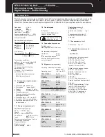
Страница 10: ...Overvoltage protection Transzorb diodes Electric strength GND to housing 500 V Control arm optional BTL2 GS08 _ _ _ _ A Aluminum dimensions Fig 3 8 Various standard lengths LS available please specify...

Страница 11: ...gs and M5 x 22 cylinder head screws DIN 912 max tightening torque 2 Nm NL Nominal stroke Fig 3 2 BTL5 P 3800 2 magnet Fig 3 4 BTL5 P 4500 1 electromagnet 24 V 100 mA Fig 3 3 BTL5 P 5500 2 magnet max p...

Страница 12: ...th American Headquarters Balluff Inc 8125 Holton Drive Florence KY 41042 Phone 859 727 2200 Toll free 1 800 543 8390 Fax 859 727 4823 Web www balluff com E Mail balluff balluff com Canada Balluff Cana...

Отзывы: