background image

WWW.BALLUFF.COM 

 • 

 1-800-543-8390

BTL5-P/I/K/L/M_-

M/U_ _ _ _-P-S32/KA_ _

Micropulse Linear Transducer

Digital Output / Profile Housing

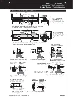
7   Magnet and Control Arm Diagram Refernces

55

28

45

21

Ø 4.2

20

61 +10

1

15

E

E

C

D

Fig. 3-1: Dimensional
drawing (BTL5...P-S 32
transducer with floating
magnet BTL5-P-3800-2)

NL

Nominal stroke

Mounting brackets with isolation bushings and M5 x 22 cylinder
head screws, DIN 912, max. tightening torque 2 Nm

Fig. 3-5: Dimensional
drawing (BTL5...P-KA
transducer with captive
magnet BTL5-F-2814-
1S)

Mounting brackets with isolation bushings and M5 x 22 cylinder head
screws, DIN 912, max. tightening torque 2 Nm

NL

Nominal stroke

Fig. 3-2: BTL5-P-3800-2 magnet

Fig. 3-4: BTL5-P-4500-1
electromagnet (24 V/100 mA)

Fig. 3-3: BTL5-P-5500-2 magnet

max. permissible
tightening torque 2 Nm

Ball joint "B"
DIN 71805,
rotates horizontally

Black, round
marking

Fig. 3-6: BTL5-F-2814-1S magnet

Fig. 3-7: BTL5-M/N-2814-1S magnet

Mechanically joined to M5
stud using 2 nuts

Max. angle offset

Max. parallel offset

BTL5-M-2814-1S:   X = 48.5     Y = 57
BTL5-N-2814-1S:    X = 51        Y = 59.5

straignt

BKS-S 32M-00

right-angle

BKS-S 33M-00

Cable entry
(PG 9 fitting)

Fig. 4-1: Connector (optional)

Jam nut DIN 934 M5

Swivel eye DIN 648

Ball joint "B" DIN 71805,
rotates horizontally (part of
BTL5-F-2814-1S) magnet)

Fig. 3-8: BTL2-GS08-_ _ _ _-A
connecting rod

Содержание BTL5-P

Страница 1: ...Sensors Worldwide BTL5 P I K L M_ M U_ _ _ _ P S 32 KA_ _ Micropulse Linear Transducer Digital Output Profile Housing Technical Description User s Guide...

Страница 2: ......

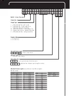
Страница 3: ...stop with tri state Differential stop leading edge active Differential pulse width modulated Differential start stop leading edge active Single ended start stop leading edge active Differential start...

Страница 4: ...stallation 3 3 2 Floating magnets 4 3 3 Captive magnets 5 4 Wiring 6 5 Startup 7 5 1 Check connections 7 5 2 Turning on the system 7 5 3 Check output values 7 5 4 Check functionality 7 5 5 Fault condi...

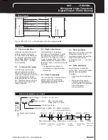
Страница 5: ...provides an unreliable signal but which may be entered The electrical connection between the transducer the processor controller and the power supply is via a cable which depending on the version is...

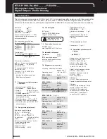
Страница 6: ...is attached to the moving member of the machine using non magnetizable screws brass aluminum To ensure the accuracy of the transducer system the moving member must carry the magnet on a track paralle...

Страница 7: ...5 stud using 2 nuts Max angle offset Max parallel offset BTL5 M 2814 1S X 48 5 Y 57 BTL5 N 2814 1S X 51 Y 59 5 3 3 Captive magnets Lateral forces are to be avoided when using captive magnets Figs 3 6...

Страница 8: ...d power supply avoid proximity to high voltage lines to prevent noise coupling Especially critical is inductive noise caused by AC harmonics e g from phase control devices against which the cable shie...

Страница 9: ...the replacement or repair are found a correction should be made Transducers are subject to modification or manufacturing tolerances 5 4 Check functionality The functionality of the transducer system...

Страница 10: ...Overvoltage protection Transzorb diodes Electric strength GND to housing 500 V Control arm optional BTL2 GS08 _ _ _ _ A Aluminum dimensions Fig 3 8 Various standard lengths LS available please specify...

Страница 11: ...gs and M5 x 22 cylinder head screws DIN 912 max tightening torque 2 Nm NL Nominal stroke Fig 3 2 BTL5 P 3800 2 magnet Fig 3 4 BTL5 P 4500 1 electromagnet 24 V 100 mA Fig 3 3 BTL5 P 5500 2 magnet max p...

Страница 12: ...th American Headquarters Balluff Inc 8125 Holton Drive Florence KY 41042 Phone 859 727 2200 Toll free 1 800 543 8390 Fax 859 727 4823 Web www balluff com E Mail balluff balluff com Canada Balluff Cana...

Отзывы: