Receiving & Installation 3-7
MN1213
5.
Repeat steps 1, 2, 3 and 4 for each of the tachometers and be sure to
use the Phoenix Connector for the correct Axis.
6.
Differential Command Input – Connect the input Velocity Command
Signal to pin 1 and its return to pin 4. Ensure that jumper P2 is in its right
most position (pins 1 and 2).
Single Ended Command Input – Connect the Velocity Command Signal
to pin 4 and its return to pin 2. Ensure that jumper P2 is in its left most
position (pins 2 and 3).
7.
Repeat for each axis and be sure to use the Phoenix Connector for the
correct Axis.
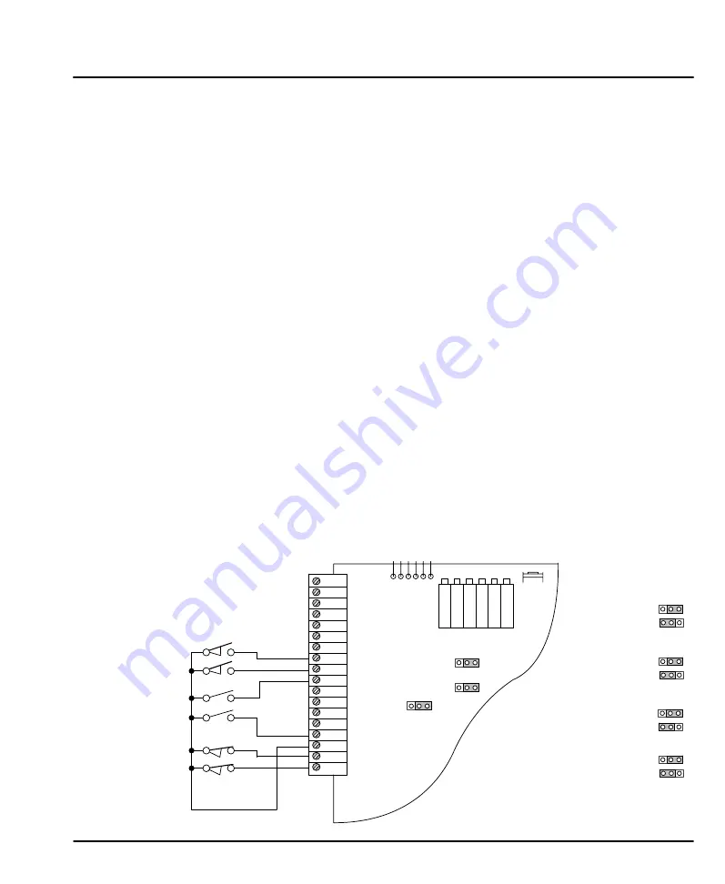
Limit, Interlock and Reset Switches (Refer to Figure 3-7).
When the left or right limit is activated, motor rotation in that direction is not
allowed. An activated limit switch disables the amplifier and the motor will coast to
a stop. This function can be used for an axis over–travel limit to prevent further
operation in the inhibited direction, but it does allow the control to back out of the
limit (rotate in the opposite direction).
1.
Connect a normally open switch to pins 8 & 9. Or, if you use normally
closed switches, connect these to pins17 & 18.
2.
Set jumper P1 for normally open or closed operation.
Note: If Pl is in the left position (normally closed) and no limit switches are
connected, the control will assume the limit switch has opened and disable
its output in that direction (i.e. the control will not operate).
3.
Connect the switch common to pin 16.
Steps 4 and 5 are optional input connections.
4.
Connect the interlock switch to pin 10.
5.
Connect the reset switch to pin 15.
6.
Repeat steps 1, 2, 3, 4 and 5 for each axis.
Figure 3-7 Limit, Reset and Interlock Connections
1
2
3
4
5
6
7
8
9
10
11
12
13
14
15
16
17
18
Differential
Common
Auxiliary Input
Signal Input
Tach + Input
Tach - Input
Decoupled Current Sense
Left Limit (Normally Open)
Right Limit (Normally Open)
Interlock
Common
+15VDC
Common
-15VDC
Reset
Common
Left Limit (Normally Closed)
Right Limit (Normally Closed)
1
P1
1
P2
1
P3
A S T R C B
1 2 3 4 5 6
Test Points
Normally Open
Normally Closed
Limit Circuit P1
Phoenix
Connector
On
Off
Actual
Absolute
Current Monitor Value DCS P3
Differential Input P2
Latch
Foldback
EC Fault Function P4
Potentiometers
Normally Open Limits
Left
Right
Normally Closed Limits
Left
Right
Interlock
Reset
Reset
SW1
Содержание UM Series
Страница 2: ...UM Series DC Servo Control SERVO DRIVE Installation Operating Manual 4 00 MN1213...
Страница 4: ...ii Table of Contents MN1213...
Страница 20: ...3 10 Receiving Installation MN1213...
Страница 24: ...4 4 Adjustments Start Up MN1213...
Страница 28: ...5 4 Troubleshooting MN1213...
Страница 31: ...Specifications Product Data 6 3 MN1213...
Страница 32: ...6 4 Specifications Product Data MN1213...
Страница 33: ...Specifications Product Data 6 5 MN1213 Dimensions Inches mm UM4 shown Height 7 25 184 15...
Страница 34: ...6 6 Specifications Product Data MN1213...
Страница 38: ...A 4 Product Overview MN1213...
Страница 40: ...UM Series DC Servo Control MN1213...


