2
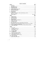
TABLE OF CONTENTS
Section Page
1 Introduction ..........................................................................................................................4
Safety
Notice
................................................................................................................. .....11
2 Quick-Start
Instructions ........................................................................................................13
3 Mounting
Instructions ...........................................................................................................15
4 Electrical
Connections............................................................... ..........................................16
5
Important Application Information ........................................................................................23
6
Setting Selectable Jumpers .................................................................................................23
7 Start-Up
and
Adjustments ....................................................................................................29
8 Drive
Operation ....................................................................................................................33
9 Diagnostic
LED’s ..................................................................................................................34
10 Troubleshooting ...................................................................................................................34
Appendix A - Modification for Subfractional Horsepower Motors.................................... ....36
Baldor District Offices...........................................................................................................39
Limited Warranty ................................................................................................. Back Cover
Tables
Page
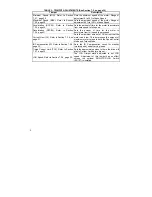
1 Standard
Features ...............................................................................................................5
2 Selectable
Jumpers..............................................................................................................5
3 Trimpot
Adjustments ............................................................................................................6
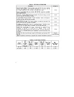
4 Optional
Accessories ...........................................................................................................7
5 Electrical
Ratings .................................................................................................................7
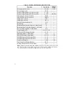
6
General Performance Specifications....................................................................................8
7 Armature
Fuse
Chart............................................................................................................17
8 Terminal
Block Wiring ..........................................................................................................17
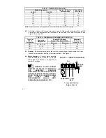
9
Field Connections ................................................................................................................18
10 Drive Operating Condition and Run/Fault Relay Contact Status .........................................22
11 Relationship of AC Line Input and Motor Voltage with Jumper J2 and J3 Position .............27
12 Jumper J4 Setting vs. Motor Horsepower ............................................................................27
13 Current Limit Settings with 0.5 Ohm Plug-In Horsepower Resistor Installed .......................28
14 Troubleshooting Guide .........................................................................................................34
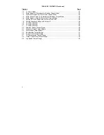
Figures
Page
1
Cover
Layout ......................................................................................................................9
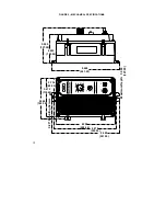
2
Mechanical
Specifications..................................................................................................10
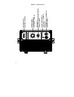
3
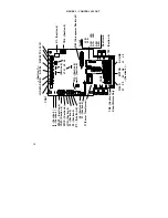
Control
Layout ....................................................................................................................14
4
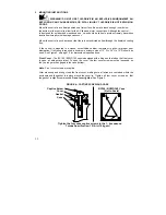
Captive Screw and Case....................................................................................................15
5
Connection
Diagram ..........................................................................................................17
6A Full Voltage Field ...............................................................................................................18
6B Half Voltage Field...............................................................................................................18
7
Tachometer
Connection
Diagram ......................................................................................19
8A Remote Potentiometer Connection ....................................................................................19
8B Analog Voltage Connection................................................................................................19
9
Remote Start/Stop Switch Connection...............................................................................20
10A Inhibit Circuit Wiring ...........................................................................................................21
10B Enable Circuit Wiring..........................................................................................................21
11
Run/Fault
Relay
Connections ............................................................................................22
Содержание NEMA-4X
Страница 37: ...37 Notes...
Страница 38: ...38 Notes...


