Baldan CRI-A Скачать руководство пользователя страница 22

Instruction Manual

CRI-A

  -  20

01 - 

01 - 

Figure 7 shows the mounting of the disc sections of CRI-A 48 discs.

MOUNTING OF DISC SECTIONS (FIGURE 7)

CRI-A 48 DISCS

Figure 07

CRI-A 48 Discs

LEGENDA:

Disc

Bearing

Spool

A

B

C

A

A

C

C

B

B

A

C

B

A

C

B

Содержание CRI-A

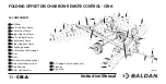
Страница 1: ...Folding Offset Disc Harrow Remote Control CRI A...

Страница 2: ......

Страница 3: ...er the responsibility to keep the protection and conservation while keep the implement in your stock and than to assembly tighten lubrication and overhaul On time of the technical deliver the dealer m...

Страница 4: ...Folding Offset Disc Harrow Remote Control CRI A...

Страница 5: ...enterframesonthestiffener figure8 CRI A40 44 48discs 21 Mountingofdiscsectionsoncenterframes figure9 CRI A40 44 48discs 22 Mountingofsideframes figure10 CRI A40 44 48discs 23 Mountingofdiscsectionsons...

Страница 6: ...hetractor Figure23 CRI A40 44 48discs 36 07 Transportation work 37 Transportation figures24 CRI A40 44 48discs 37 Work figures25 CRI A40 44 48discs 39 08 Adjustments 41 Harrowspacingadjustments figure...

Страница 7: ...table2 CRI A40 44 48discs 50 Bearingadjustments figure36 CRI A40 44 48discs 53 Bearinglubrication 53 11 Calculations 54 ApproximatehourlyproductionCRI A40 44 48discs 54 Approximatehourlyproductiontab...

Страница 8: ...NTION TO THE POSSIBILITY OF PERSONAL ACCIDENTS Carefully read the instructions manual toknow the recommen dedsafetypractices Only start operating the trac tor when you are duly accom modated and with...

Страница 9: ...any mainte nanceonyourequipment check ifitisatastandstill Avoidbeinghit ATTENTION When searching for a possible leak on the hoses use a piece of cardboard or wood and never useyourhands Avoidtheincis...

Страница 10: ...fdamagesandaccidents NR 31 OCCUPATIONAL SAFETY AND HEALTH IN AGRICULTURE LIVESTOCK FORESTATION FOREST EXPLORATION AND AQUICULTURE This objective of this Regulatory Standard is to establish the precept...

Страница 11: ...Immediately replace it in the case of leaks because the oil operates at high pressure and can cause serious injuries 05 05 Do not use loose clothing as it can get caught on the equipment 06 06 When ac...

Страница 12: ...terconnected 13 13 Do not work with the tractor if the front is light Add weights to the front or front wheels in case it may be raised 14 14 When leaving the tractor put the brake handle in the neutr...

Страница 13: ...side back frame 06 Center back frame 07 Right side back frame 08 Coupling header 09 Articulation shaft support 10 Tires 11 Discs 12 Wheel articulation pistons 13 Side articulation pistons 14 Stabiliz...

Страница 14: ...tructionManual CRI A 12 03 DIMENSIONS DIMENSIONS CRI A 40 44 DISCS FIGURES 2 Figures02 3352 mm CRI A 40 Discs 3423 mm CRI A 44 Discs 3405mm CRI A40 44Discs 335 mm CRI A 40 44 Discs 6985mm CRI A40 44Di...

Страница 15: ...InstructionManual 13 CRI A Figures02 DIMENSIONS CRI A 40 44 DISCS CONTINUATION 5283 mm CRI A 40 Discs 5795 mm CRI A 44 Discs 7400mm CRI A40Discs 7501mm CRI A44Discs...

Страница 16: ...InstructionManual CRI A 14 DIMENSIONS CRI A 48 DISCS FIGURES 3 Figures03 2995 mm CRI A 48 Discs 4237mm CRI A48Discs 323 mm CRI A 48 Discs 7832mm CRI A48Discs...

Страница 17: ...InstructionManual 15 CRI A Figures03 DIMENSIONS CRI A 48 DISCS CONTINUATION 6372 mm CRI A 48 Discs 8290mm CRI A48Discs...

Страница 18: ...0 270 26 e 28 6 0 e 7 5 1 5 8 5290 150 250 0 5440 240 260 Duplo 400x60 CRI A 44 270 26 e 28 6 0 e 7 5 1 5 8 5840 150 250 0 5650 264 280 CRI A 48 270 26 e 28 6 0 e 7 5 1 5 8 6390 150 250 0 6000 288 303...

Страница 19: ...the set is complete with all the discs bearings separator spools put the convex thrust washer 10 the other washer 3 and nut 4 tightening with the key until the entire set is firmly secured 04 04 Then...

Страница 20: ...ual CRI A 18 Disc Bearing Spool 01 01 Figure 5 shows the mounting of the disc sections of CRI A 40 discs MOUNTING OF DISC SECTIONS FIGURE 5 CRI A 40 DISCS Figure05 CRI A40Discs LEGEND A B C A A C C B...

Страница 21: ...ual 19 CRI A 01 01 Figure 7 shows the mounting of the disc sections of CRI A 44 discs MOUNTING OF DISC SECTIONS FIGURE 6 CRI A 44 DISCS Figure06 CRI A44Discs LEGEND Disc Bearing Spool A B C A A C C B...

Страница 22: ...ual CRI A 20 01 01 Figure 7 shows the mounting of the disc sections of CRI A 48 discs MOUNTING OF DISC SECTIONS FIGURE 7 CRI A 48 DISCS Figure07 CRI A48Discs LEGENDA Disc Bearing Spool A B C A A C C B...

Страница 23: ...unting the CRI A with the center frames proceeding as follows 3 1 5 4 6 8 7 01 01 Put the front center frames 1 and back cen ter frames 2 on a flat and clean place 02 02 Then put the stiffener 3 on th...

Страница 24: ...row and coincide the holes of the wedges 4 with the bearings then secure using the bolts 5 flat washer 6 pressure washer 7 and nut 8 02 02 Then raise the other part of the harrow and repeat the operat...

Страница 25: ...01 01 Couple the side frames 1 to the cen ter frames 2 02 02 Then insert the pins 3 securing using at washers 4 and nuts 5 loc king using the bolts 6 and nuts 7 03 03 Finish by placing the supports 8...

Страница 26: ...then secure using the bolts 5 flat washer 6 pressure washer 7 and nut 8 02 02 Then raise the other part of the harrow and repeat the operation checking the concavity of the discs of one section to th...

Страница 27: ...ounting the disc sections on the frames attach the cleaners 1 proceeding as follows 3 1 4 6 5 2 01 01 Put the cleaners 1 on the frames 2 securing them with bolts 3 flat washers 4 pressure washers 5 an...

Страница 28: ...essure washers 5 and nuts 6 02 02 Then couple the shaft support 7 to the articu lation shaft of the tires 2 securing using the pin 9 pressure washer 10 and bolts 11 03 03 After place the bars 12 on th...

Страница 29: ...upport on the stiffener attach the tires 1 proceeding as follows 01 01 Couple the tires 1 to the wheel support 2 using the bolts 3 and nuts 4 Figure14 3 1 2 4 Detail A All the tires should be mounted...

Страница 30: ...pins 9 washers 10 and retai ning pin 11 03 03 Then couple the stabilizer bar support 12 to the header 1 using the bolt 13 pressure washer 14 and nut 15 04 04 Afterwards insert the pin 16 in the heade...

Страница 31: ...ttach the adjusting rod 1 proceeding as follows 01 01 Attach the back part of the adjusting rod 1 to the articulation shaft 2 using the pin 3 flat washer 4 and retaining pin 5 02 02 Then attach the fr...

Страница 32: ...r mounting the adjusting rod attach the central hydraulic cylinders proceeding as follows 01 01 Couple the bases of the hydraulic cylinders 1 to the stiffener 2 with the pins 3 flat washers 4 and reta...

Страница 33: ...aulic cylinders attach the side hydraulic cylinders proceeding as follows 01 01 Couple the bases of the hydraulic cylinders 1 to the side frames 2 with the pins 3 pressure washers 4 and bolts 5 02 02...

Страница 34: ...linders attach the internal hydraulic cylinders proceeding as follows 01 01 Couple the hydraulic cylinders 1 to the locks 2 with the pins 3 flat washers 4 and retaining pins 5 1 Figure19 MOUNTING OF I...

Страница 35: ...48 DISCS After mounting the coupling header attach the sign plate 1 proceeding as follows 01 01 Attach the sign plate 1 to the support 2 using the bolts 3 pressure washers 4 and nuts 5 Figure20 5 3 4...

Страница 36: ...e control Mang 3 8 x2400mm Mang 3 8 x2000mm Mang 3 8 x1800mm Mang 3 8 x2900mm Mang 3 8 x8000mm Mang 3 8 x2200mm Mang 3 8 x1800mm Tractor returntotank Pressure Tractor Pressure Tractor Tractor returnto...

Страница 37: ...control Mang 3 8 x2900mm Mang 3 8 x2400mm Mang 3 8 x2200mm Mang 3 8 x3300mm Mang 3 8 x8000mm Mang 3 8 x2200mm Mang 3 8 x1800mm Tractor returntotank Pressure Tractor Pressure Tractor Tractor returntota...

Страница 38: ...ystem of the tractor COUPLINGTHE HARROWTOTRACTION BAR OFTHETRACTOR FIGURE 23 CRI A 40 44 48 DISCS 06 COUPLING To couple the CRI A to the traction bar of the tractor follow the instructions below Figur...

Страница 39: ...t of all operate the hydraulic cylinders 1 in order for these to move the support 2 unlocking the side frames 3 02 02 Then articulate the side frames 3 Figures24 1 2 3 When articulating the CRI A avoi...

Страница 40: ...8 with the bolt 9 and wing nut 10 6 03 03 Afterwards operate the rods of the hydraulic cylinders 4 to the necessary measurement 04 04 Put the lock 5 on the rods of the hydraulic cylinders 4 until it...

Страница 41: ...perate the hydraulic cylinders 2 in order for these to move the support 3 locking the side frames 1 Figures 25 2 3 1 WhendisarticulatingtheCRI A avoidhavingpeopleclosetoitbecauseof the risk of acciden...

Страница 42: ...rods and the plungers of the hydraulic cylinders 4 05 05 After working with the CRI A remove the limiting rings 5 from the hydraulic cylinders 4 After adjustment the CRI A will always operate at the...

Страница 43: ...S To obtain the ideal penetration of the discs the harrow spacing should be adjusted and this varies with the type of soil On lands of greater penetration diculty increa se the harrow spacing On light...

Страница 44: ...loosen the nuts 1 pressure washers 2 and flat washers 3 and remove the locks 4 and bolts 5 02 02 Then adjust the frames 6 reducing or increasing the opening 03 03 After attach it back to the stiffene...

Страница 45: ...s not giving a perfect finish meaning that it is leaving a trail of the tractor In order for the harrow to work centralized with the traction line of the tractor proceed as follows 01 01 Loosen the nu...

Страница 46: ...ENT FIGURE 28 CRI A 40 44 48 DISCS 01 01 The stiffener 1 has two holes on each side with the main purpose of leveling the header of the harrow in relation to the traction bar of the tractor 01 01 Incr...

Страница 47: ...the stabilizer rod 1 leave a gap of 10 to 20 mm between the nut and the surface of the spring as shown in detail A 02 02 On the support 2 of the stabilizer bar leave a gap of 10 to 20 mm between the s...

Страница 48: ...l the bolts and nuts after every 10 hours of work 01 02 03 04 Adjust the tractor according to the content of the instruction manual always using the front and back weights to stabi lize the equipment...

Страница 49: ...ation with the terrace on the left side of the trac tor operator 02 02 Do not turn to the right the harrowed land must always be to the left of the tractor operator Figure30 HARROWING CRI A 40 44 48 D...

Страница 50: ...t another plot when moving a lot on the headers PLOTSWITH CONTOUR LINES FIGURE 32 CRI A 40 44 48 DISCS 01 01 On lands with contour line it is normal to start two plots at a time care fully starting th...

Страница 51: ...re33 Excess Pressure Lackof Pressure Correct Pressure Constantly check the nuts and bolts and retighten if necessary General retightening maintenance of the equipment should be performed every 8 worki...

Страница 52: ...n to its ef ficiency and purity avoiding the use of products contaminated with water soil and other agents TABLE OF GREA SE AND EQU IVALENT PRODUCTS Manufacturer Typesofgreaserecommended Petrobr s Lub...

Страница 53: ...InstructionManual 51 CRI A LUBRICATE EVERY 24 HOURS OFWORK FIGURES 34 CRI A 40 44 48 DISCS Figures34 When lubricating the CRI A do not use excess quantity of new grease Add a sucient amount ATTENTION...

Страница 54: ...44 48 DISCS LUBRICATE EVERY 60 HOURS OFWORK FIGURE 35 CRI A 40 44 48 DISCS Figures34 Figure35 When lubricating the CRI A do not use excess quantity of new grease Add a sucient amount ATTENTION Whenlub...

Страница 55: ...ould rotate freely without slacks 1 4 2 3 BEARING ADJUSTMENTS FIGURE 36 CRI A 40 44 48 DISCS Figure36 Donotmountthebearingwithoutjoints 4 BEARING LUBRICATION 01 01 On the rst days of work with the CRI...

Страница 56: ...000 m the value varies according to the region A L 6 39m V 7 000m h F 0 90 X 10 000 m2 Calculated in hectares A 6 39 x 7 000 x 0 90 4 02 Ha h 10 000 APPROXIMATE HOURLY PRODUCTION CRI A 40 44 48 DISCS...

Страница 57: ...calculate the approximate production refers to the calculation of areas to be worked or areas worked per harrow To know the time spent working an area of known value divide the value of this area by...

Страница 58: ...arts do not present wears If replacement is required always demand for original Baldan parts 07 07 Always keep the CRI A discs sharp 01 01 When storing the CRI A carry out general cleaning and wash it...

Страница 59: ...entification tag ALWAYSREQUIREBALDANORIGINALPARTS Look in your local a reseller BALDAN he will have in stock genuine parts Code 6055010371 3 CPT CRIA013319A PUBLICATIONS The draws contained in this in...

Страница 60: ..._________________________________________________________________________________________________ City __________________________________________________________________ Country ______________________...

Страница 61: ...InstructionManual 59 CRI A 13 NOTES...

Страница 62: ...we conclude that it wasn t a guarantee problem then the dealer will be the responsible for all costs related to the replacement as well as material expenses travel including accommodation and meals al...

Страница 63: ...nforme detailed telling the problem technical assistance request form to the client you can find it send us an email to after sales baldan com br or acessing our website 13 13 If it s possible send fi...

Страница 64: ......

Страница 65: ...___________________________ City __________________________________________________________________ State __________________________________ Zip code _______________________ Owner ____________________...

Страница 66: ......

Страница 67: ..._____________ City __________________________________________________________________ State _________________________________________________________________ E mail ___________________________________...

Страница 68: ......

Страница 69: ..._________________________________________________ State _________________________________________________________________ E mail _______________________________________________________________________...

Страница 70: ......

Страница 71: ......

Отзывы: