background image

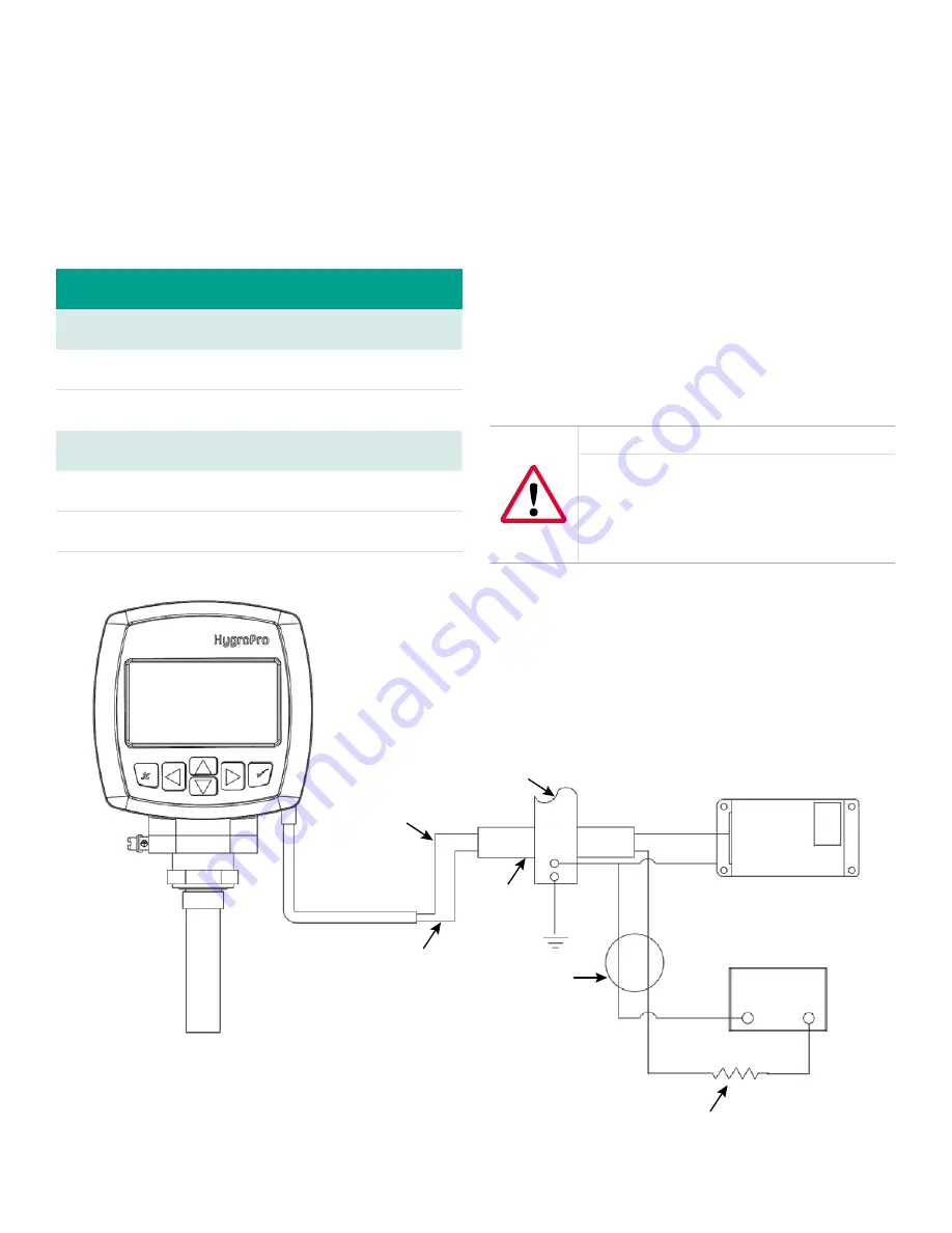
Bus bar

Brown

Blue

Red

3

4

1

2

+24V

24V return

+

OCB(*)

Green

Black

Black

IS ground

R1, 250 ohms, ±5%, 1/4 Watt

MTL706

Power supply

4 - 20 mA

Analog input device

Figure 6: Hazardous area connections

1.4.2d Requirements for external devices

When connecting the 

HygroPro

 to external devices, the 

allowable total load capacitance and inductance for  

those devices are listed in the manufacturer’s datasheets. 

The entity parameters of the external devices (e.g. voltage, 

current and power) must be equal to or lower than the  

same specifications for the 

HygroPro

.

The entity parameters for the 

HygroPro

 are listed in  

Table 5 below.

Table 5: HygroPro entity parameters

Loop power supply

U

i

 = 28 V

P

i

 = 0.653 W

L

i

 = 62 µH

I

i

 = 93.3 mA

C

i

 = 0

RS485 digital output

U

i

 = 3.72 V

P

i

 = 212 mW

L

i

 = 62 µH

I

i

 = 228 mA

C

i

 = 67 µF at 5.36 V

1.4.2e Special conditions for safe operation

The “X” at the end of the 

HygroPro

 ATEX certificate number, 

Bas06ATEX0019X

, indicates that special conditions are 

required for safe operation in Europe. These conditions are:
1.  The equipment must be protected against impact or 

friction with ferrous metals.

2.  The bare ends of the connecting cable must be 

terminated in such a way that the terminations are 

afforded a degree of protection of not less than IP20 

ingress protection.

3.  The 

HygroPro

 is incapable of withstanding the 

500 VAC test between all inputs and frame for one 

minute. Therefore, the 

HygroPro

 must be earthed by 

connecting the outer grounding screw on the 

HygroPro


with the equipotential bonding system. Follow the 

local standards and electrical codes regarding the 

equipotential bonding system.

WARNING!

Never connect or disconnect the HygroPro in 

the hazardous area when supply power or the 

communication circuit is energized. Isolate 

the supply lines in the non-hazardous area 

first.

Following the same special conditions listed above is 

recommended for regions outside of Europe as well.

8

Содержание Panametrics HygroPro

Страница 1: ...HygroPro User s manual 916 099 Rev D...

Страница 2: ...ii...

Страница 3: ...HygroPro Moisture transmitter User s manual 916 099 Rev D November 2012 iii...

Страница 4: ...no content intended for this page proceed to next page iv...

Страница 5: ...1 2 2 3 Selecting measurement parameters 11 2 2 4 Setting up the display 12 2 2 5 Setting up the analog output 12 2 2 6 Entering the node ID 13 2 2 7 Setting up the RS485 output 13 2 3 Advanced setup...

Страница 6: ...the cleaned probe 18 Chapter 4 Specifications 19 4 1 General 19 4 2 Electrical 19 4 3 Mechanical 19 4 4 Moisture sensor 19 4 5 Built in temperature sensor 20 4 6 Built in pressure sensor 20 4 7 Certi...

Страница 7: ...t the following link https www bakerhughesds com sales terms conditions Typographical conventions Note These paragraphs provide information that provides a deeper understanding of the situation but is...

Страница 8: ...ke sure that unauthorized personnel cannot gain access to the operation of the equipment Environmental compliance RoHS The HygroPro moisture transmitter fully complies with RoHS regulations Directive...

Страница 9: ...x button keypad and it is housed in an IP67 Type 4X enclosure The HygroPro transmitter uses an aluminum oxide moisture sensor and it includes a temperature thermistor and a pressure transducer on a co...

Страница 10: ...he sample flow Before constructing a sample system consult a Panametrics application engineer and observe the following guidelines The sample system should be very simple and should contain as few com...

Страница 11: ...age during operation 2 Using the integral 3 4 16 straight male thread screw the probe end of the transmitter into the process or sample system fitting Make sure not to damage the threads Note A 3 4 16...

Страница 12: ...receive and display the 4 20 mA measurement output from the HygroPro proceed to next page an external power supply to provide power to the HygroPro plus a personal computer PC running Panametrics Pan...

Страница 13: ...ground 1 Connect an RS485 RS232 converter customer supplied to an available serial port on the PC 2 Push the female connector end of the factory supplied cable into the mating male connector on the t...

Страница 14: ...da for the following hazardous classified locations and protection methods Intrinsically safe class I II III division 1 group ABCDEFG T4 T Ambient 40 C to 60 C Enclosure IP 67 3 Galvanically isolated...

Страница 15: ...C22 2 No 61010 1 Degrees of Protection Provided by Enclosures IP Code ANSI IEC 60529 Degrees of Protection Provided by Enclosures IP Code CSA C22 2 No 60529 1 4 2b Compliance requirements The HygroPr...

Страница 16: ...e end of the HygroPro ATEX certificate number Bas06ATEX0019X indicates that special conditions are required for safe operation in Europe These conditions are 1 The equipment must be protected against...

Страница 17: ...plied to the unit The transmitter requires up to 60 seconds to initialize and begin normal operation The unit will meet its specified accuracy within 3 minutes Figure 7 below shows a close up view of...

Страница 18: ...st temperature Node ID enter value Baud rate Parity Stop bits Data Bits Save Table RS485 Service Zero mV Zero PSIg Span mV Span PSIg Temp C 6 CS 6 Temp C 1 CS 1 Row 16 Units 16 Row 1 Units 1 Figure 8...

Страница 19: ...level passcode must be entered 2 2 3 Selecting measurement parameters To select the measurement parameters complete the following steps To select the number of measurements to be displayed on each scr...

Страница 20: ...he above screen highlight that choice and press enter Use the arrow keys to change the contrast value and press enter Then press escape twice to return to the main menu 2 2 5 Setting up the analog out...

Страница 21: ...twork when used with PanaView interface software To enter your nNode ID proceed as follows Enter your passcode to access the setup program Then use the arrow keys to select the Node ID menu Press ente...

Страница 22: ...o enter the desired pressure value and press enter The screen will be updated to show the new pressure value To set the temperature display enter your password and use the arrow keys to select const t...

Страница 23: ...to select lock keypad on the initial screen and press enter twice The keypad is now locked To unlock the keypad just re enter the user program as described on page 11 No further programming steps are...

Страница 24: ...creen instructions After completing the above step respond to the ARE YOU SURE question Be sure to respond yes if you wish to save the new information 3 2 Moisture probe error conditions IMPORTANT All...

Страница 25: ...al depends on the specific application To accomplish this either return the RTE to Panametrics for recalibration or install a new RTE The HygroPro electronics will automatically read and store the cal...

Страница 26: ...n set at 50 C 2 C 122 F 3 6 F for 24 hours 3 3 6 Installing the probe in the transmitter To install a new or cleaned probe in the transmitter complete the following steps 1 Reconnect the probe cable t...

Страница 27: ...iven a 24 VDC power supply Max load resistance 24 x 33 33 300 500 Cable 6 ft 2 m standard consult Panametrics for custom lengths Input parameters for loop powered intrinsic safety Ui 28V Pi 0 653W Li...

Страница 28: ...lable ranges 30 to 300 psig 3 to 21 bar 50 to 500 psig 4 to 35 bar 100 to 1000 psig 7 to 69 bar 300 to 3000 psig 21 to 207 bar 500 to 5000 psig 35 to 345 bar Note Psig ranges are based on a constant p...

Страница 29: ...s arising from course of dealing or usage or trade Return policy If a Panametrics instrument malfunctions within the warranty period the following procedure must be completed 1 Notify Panametrics givi...

Страница 30: ...uction targets across critical industries including Oil Gas Energy Healthcare Water and Wastewater Chemical Processing Food Beverage and many others Join the conversation and follow us on LinkedIn lin...

Отзывы: