Masoneilan 49000 Series Energy Management Control Valves | 7
Copyright 2020 Baker Hughes Company. All rights reserved.
2. Assemble the seat ring (5) or seat ring diffuser (Not Shown)
into the valve body on top of the seat ring gasket (10B),
ensuring that the threaded lifting holes are facing up.
Trim, Bonnet and Body Assembly
1. Place pinned plug stem assembly vertically on stable surface.
Carefully lift cage (4) and lower over plug stem assembly.
(Threaded holes are provided in cage for lifting).
2. Attach lifting eye to stem attach thread. Lift plug stem and
cage together using lifting eye. (Plug will stop against shoulder
inside of cage).
3. Carefully lower plug stem assembly and cage into the body
until the cage contacts the seat ring. Be sure that the cage
is aligned with and fully seated against the seat ring (5) and
that the seat gasket (10B) and cage gasket (10A) are in place.
Continue to lower until plug is seated and remove hoist and lift
eye.
Note: Correctly assembled valves with in specification
components should pass leakage testing with no lapping
of the plug to seat-ring. In the rare instance that a valve
does not shut off, light lapping of the plug to seat is
allowed as a repair.
Balance Seal Installation (B019)
Flow to open installation (FTO):
1. Ensure that the plug and the seal groove are clean and free of
sharp edges.
2. Lightly lubricate the seal (14), backup rings (22), top of plug
and seal groove with Dow Corning 111 or equivalent.
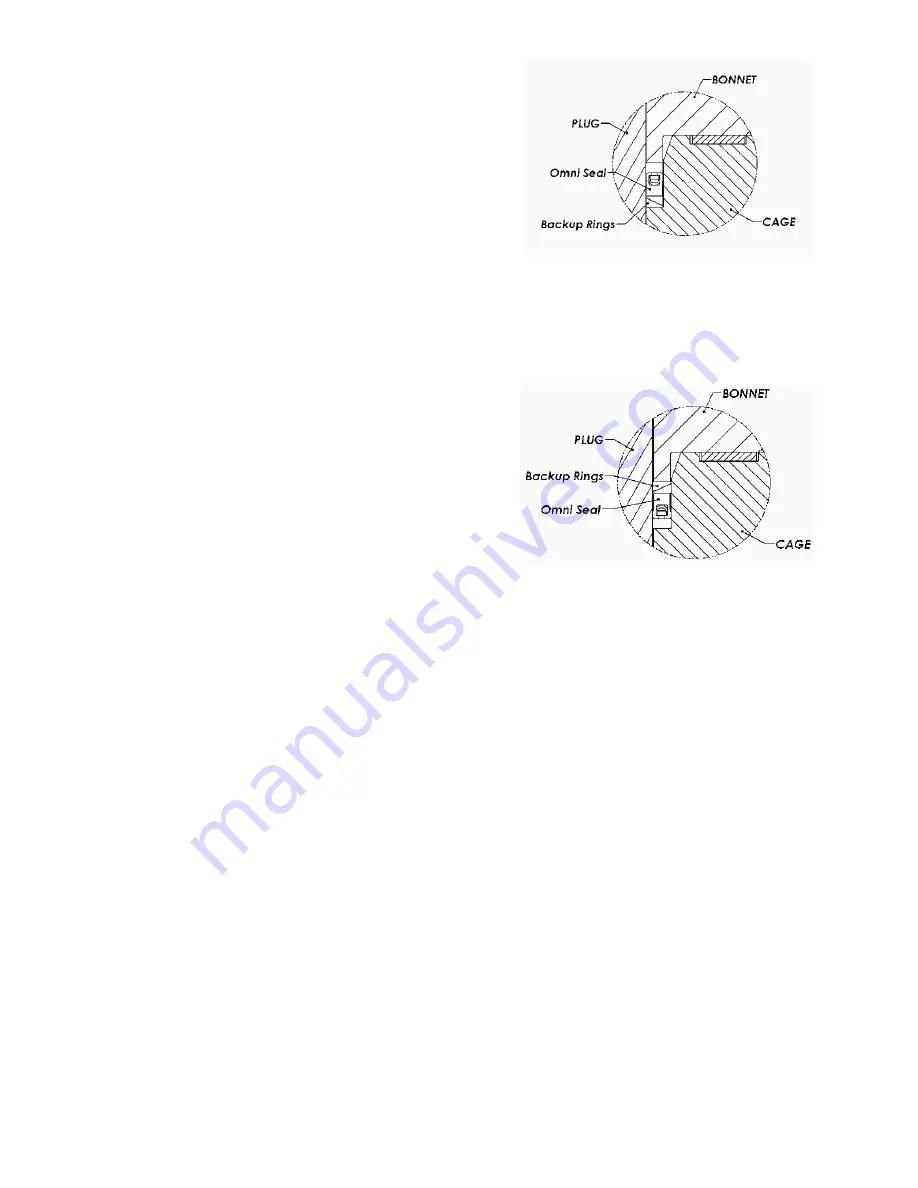
3. Position the two backup rings over plug and seat them in the
groove as illustrated. Slip the Omni seal (14) over the plug
ensuring that the open (cup) end of the seal faces up and
seats against the backup rings. (See Figure 5a.)
Flow to close installation (FTC):
1. Ensure that the plug and the seal groove are clean and free of
sharp edges.
2. Lightly lubricate the seal (14) backup rings (22), top of plug
and seal groove with Dow Corning 111 or equivalent.
3. Slip the Omni seal over plug ensuring that open (cup) end of
the seal faces down and seat it in the groove.
4. Position the two backup rings over plug and seat against the
Omni seal as illustrated. (See Figure 5b.)
Balance seal, metal (high temp) type FTO and FTC (seal is
non-directional):
1. Ensure that the plug and the seal groove are clean and free of
sharp edges.
2. Lightly lubricate the seal, inner and outer rings, top of plug and
seal groove with Dow Corning 111 or equivalent.
3. Slide the rings over plug and seat in the groove. Be sure to
stagger the end gaps of the inner and outer rings.
Bonnet Assembly
1. Make sure the packing (15) and guide bushing (7) have been
removed from the bonnet (2).
2. Position the bonnet (2) above the valve body (1), oriented as
shown in Figure 6.
Figure 5a: Flow to Open
For configurations designed with a two piece bonnet (bonnet
and bonnet flange):
3. Assemble the bonnet (2) over the valve stem (8) and push it
down carefully. Be careful not to damage the stem during the
assembly process.
Figure 5b: Flow to Close
4. Place the metal seal (11) over the bonnet (2) and press the
metal seal down into the groove formed between the body
and the bonnet.
5. Assemble the bonnet flange (3) over the bonnet (2) and align
the bolt holes with the body studs (12). Make sure the bonnet
flange is also aligned with the metal seal (11). Proceed to step
8.
For trim configurations designed with a single piece bonnet:
6. Install body gasket (Not Shown) on to the groove on top of the
valve body (1).
7. Assemble the bonnet (2) over the valve stem (8) and push
it down carefully to align the bolt holes with the body studs
(12). Be careful not to damage the stem during the assembly
process. Be sure the bonnet is oriented as shown in figure 6.
8. Grease the threads of the valve body studs (4) and the bearing
surfaces of the body stud nuts (13).
9. Assemble the body stud nuts (13) manually. Hand- tighten the
nuts evenly so the internal parts are held in place. The face
of the bonnet should be parallel to the upper face of the valve
body.
Tightening Body Nuts
In order to achieve perfect alignment of the body and the internal
components, it may be beneficial to provide loading to the plug
stem assembly (Items 6, 8 & 9) during tightening. This may benefit
the positioning of various parts in installations where the actuator
and trim are installed horizontally.


