3 | Baker Hughes
Copyright 2020 Baker Hughes Company. All rights reserved.
4. Unpacking
Unpack valves and accessories carefully to avoid damage. The
control valves are packed in a clean state and the valve openings
are sealed with protective caps. The caps provide protection
against dirt and damage and should not be removed until the
valve is being fitted into service.
5. Installation
Before installing the valve, clean all piping carefully, removing
all dirt, grease, oil and other residues. The sealing surfaces
between control valve and piping must be cleaned carefully and
checked to ensure they are tightened properly. Flange gaskets
should not be used.
The valve must be fitted in the line so that the flow is
through the valve body in the direction of the arrow
marked on the housing. The arrow corresponds to
flow to close direction. All 31000 Series control valves
must be fitted in this manner since flow assists in
closing the plug.
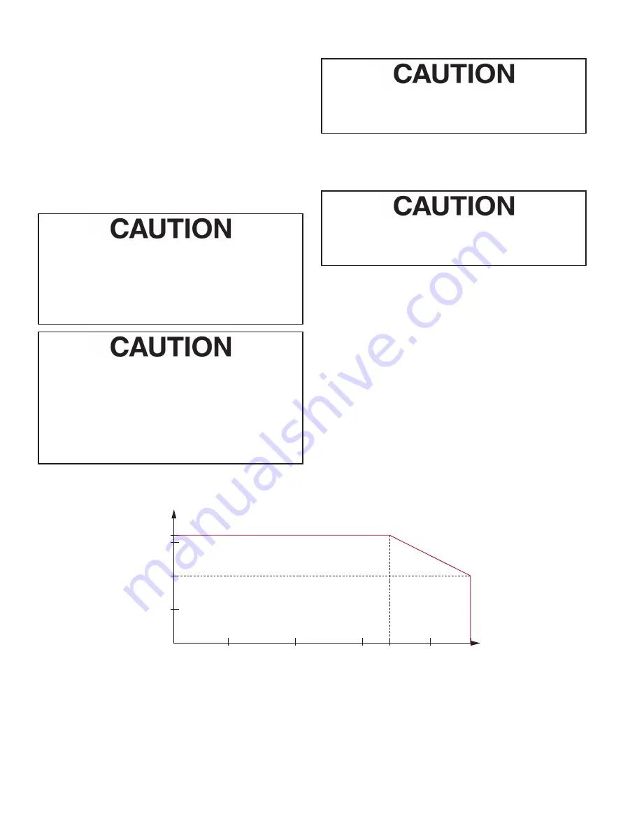
31000 Series valves are designed with a maximum
operating pressure of 232 psi (16 bar), this limit is set
by the lining. The bodies are available in different sizes
in accordance with DIN and ANSI standards. Before
fitting the control valve, the plant operator should
ensure that the maximum pressure the valve body
will be subjected to will not exceed the allowed value.
Refer to the diagram below.
6. Disassembly
Control valves, which have been in service should
be thoroughly cleaned before disassembly. Residues
present inside the valve can be harmful to health.
Note: All parts which come in contact with flow are
constructed of PTFE or PFA in standard versions of the
31000 Series. Particular care must be taken when handling
these parts since they can be easily damaged.
Prior to disassembly of the control valve, ensure that
the valve body has been depressurized. Accessories
(positioner, airset etc.) must be removed.
6.1 Actuator Disassembly
(Figure 5a and 5b)
1. Remove the rear and front covers (118 & 121) of the actuator
by releasing the screws (119). If necessary screw out the
handwheel (141) after removing the Truarc ring (138) and
washer (139).
2. Move the actuator to its intermediate position with
compressed air.
3. Remove the indicator (154), clevis pin clip (122) and clevis
pin (124), release the lever cap screw (137).
4. Depressurize the spring barrel. If the valve is not supplied
with a positioner, remove screw (127) and shaft cover (126).
5. Remove the yoke screws (19) (Figure 1) and lift off the
complete actuator unit and lever (135).
(bar)
°C
(15)
(10)
(5)
(0)
0
-20
50
100 120
150
180
°F
32
-4
122
212 248
302
356
(16)
psi
218
145
73
0
232
Pressure/Temperature Diagram


