background image

21  |  

Baker Hughes

© 2020 Baker Hughes Company. All rights reserved.

XIII. Setting and Testing (Cont.)

Air

The air leakage test shall be performed with all 

connections and openings in the body and bonnet 

pressure tight. The cap with gasket which covers 

the adjusting screw must be installed. Test valve for 

leakage using API test fixture. The API leakage test 

procedure is described below.
Per API Standard 527, (ANSI B142.1-72), a standard 

test fixture consists of a piece of tubing .313” 

(7.94mm) x .032” (0.81 mm) wall, one end of which 

is joined to an adaptor on the valve outlet and the 

other end of which is immersed .500” (12.70 mm) 

below the surface of a reservoir of water. 
The leakage rate for a valve with metal to metal 

seats shall be determined with the valve mounted 

vertically and using a standard test fixture as 

described above.
“The leakage rate in bubbles per minutes shall 

be determined with pressure at the safety relief 

valve inlet held at 90 percent of the set pressure 

immediately after popping for valves set 51 psig 

(3.517 bar) and above. On valves set at 50 psig 

(3.448 bar) and below, test for leakage at 5 psig 

(0.345 bar) below the set pressure immediately after 

popping. The test pressure shall be applied for a 

maximum of 1 minute.”
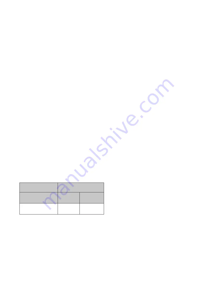
Tightness Standard: The leakage rate in bubbles per 

minute shall not exceed the following:

Max. Leakage Rate

Approx. Leakage Rate

(Bubbles / minutes)

ft

3

/ 24 Hr.

Liters/ 24 Hr.

40

0.60

16.99

Water

When a metal-to-metal seat valve is tested using 

water as the test medium, there shall be no leakage, 

as determined by seeing or feeling, when pressure is 

held at 90% of set pressure.

Steam

When a valve is checked for tightness using steam 

as the test medium, at 90% of the set pressure, 

there shall be no visual or audible leakage after the 

interior of the valve is allowed to dry after popping. 

Valve is to be held at test pressure for a minimum 

of three (3) minutes prior to checking for leakage. 

If there is no visual or audible leakage, the valve is 

acceptable.

G.  Hydrostatic Testing

When hydrostatic tests are required after installation 

of the safety relief valve, a test gag must be used. 

Very little force (fingertight) on the test gag is 

sufficient to hold hydrostatic pressures. Too much 

force applied to the gag may bend the spindle 

and damage the seat. After hydrostatic test the 

gag must be removed and replaced by the sealing 

plug furnished for this purpose. Test gags for 

Consolidated Safety Relief Valves can be furnished 

for all types of caps and lifting gears.

H.  Manual Popping

After the valve has been installed and is in use, it 

may be necessary to pop it by hand or by pressure 

to make sure it has not become fouled by chemical 

action, such as corrosion, and that it continues to 

function properly. Consolidated Safety Relief Valves 

are furnished when so ordered with packed or plain 

lifting gears for hand popping.

F.  Seat Leakage

Содержание Consolidated 1982 Series

Страница 1: ...Consolidated 1982 Series Safety Relief Valves Instruction Manual Rev B Baker Hughes Data Classification Public...

Страница 2: ...INSTRUCTIONS DO NOT PURPORT TO COVER ALL DETAILS OR VARIATIONS IN EQUIPMENT NOR TO PROVIDE FOR EVERY POSSIBLE CONTINGENCY TO BE MET IN CONNECTION WITH INSTALLATION OPERATION OR MAINTENANCE SHOULD FURT...

Страница 3: ...hts reserved All the USCS values are converted to metric values using the following conversion factors USCS Units Conversion Factor Metric Unit in 25 4 mm lb 0 4535924 kg in2 6 4516 cm2 ft3 min 0 0283...

Страница 4: ...aed 1982 Series Safety Relief Valve 10 X Disassembly 12 XI Inspection and Part Replacement 14 A Base 14 B Disc Holder 14 C Disc Retainer 15 D Guide 16 E Adjusting Ring 16 F Adjusting Screw 16 XII Reas...

Страница 5: ...ed XVI Replacement Parts Planning 23 A Basic Guidelines 23 B Identification and Ordering Essentials 24 XVII Genuine Consolidated Parts 24 XVIII Recommended Spare Parts 25 XIX Manufacturer s Service Re...

Страница 6: ...cation of Products Baker Hughes cannot be responsible for customer s incorrect selection or misapplication of our products Unauthorized Repair Work Baker Hughes has not authorized any non Baker Hughes...

Страница 7: ...ker Hughes or deviates from Baker Hughes recommendations must be thoroughly satisfied that neither personal safety nor valve safety will be jeopardized by the procedure and or tools selected If not so...

Страница 8: ...n some instances of risk to human health and safety the pictorial may instead depict what preventive measures to take such as wearing wearing the appropriate personal protective equipment PPE The bott...

Страница 9: ...ury or death 2 WARNING Always read and comply with safety labels on all containers Do not remove or deface the container Do not remove or deface the container labels Improper handling or misuse could...

Страница 10: ...tools or improper use of right tools could result in personal injury or product damage Wear necessary protective equipment to prevent possible injury Always use appropriate restoration procedures 1 C...

Страница 11: ...ith the inlet down Uncrated valves should be moved or hoisted by wrapping a chain or sling around the discharge neck then around the upper yoke structure in such manner as will ensure the valve is in...

Страница 12: ...achining may be necessary to extend the service life of a valve Keep all parts for each valve separated to ensure replacement in the same valve DANGER Insure there is no pressure in the inlet of the v...

Страница 13: ...osition when a valve is relieving G Maximum Allowable Working Pressure The maximum gauge pressure permissible in a vessel at a designated temperature A vessel may not be operated above this pressure o...

Страница 14: ...down Adjustment The Consolidated single blowdown ring design makes it possible to set and test a valve that has been in service when it cannot be set on line and must be taken to the customer s shop T...

Страница 15: ...rim 6c 6b 6a 4 5 1 7 Part No Nomenclature 1 Base 1a Inlet Flange When Applicable 2 Bonnet Gasket 3 Adjusting Ring Pin Gasket 4 Adjusting Ring Pin 5 Adjusting Ring 6 Disc Assembly 6a Disc Collar 6b Dis...

Страница 16: ...7 Release Locknut 18 Release Nut 19 Lever Pin 20 Plain Lever 21 Cap Screw 22 Packed Cap 23 Packed Lever 24 O Ring 25 Bushing 26 Cam Shaft 27 Drive Stud 28 Lever Gasket 29 Gag 30 Sealing Plug 31 Sealin...

Страница 17: ...wearing out of flatness is evident recondition the lap 3 Apply a very thin layer of compound to the lap This will prevent rounding off the edges of the seat 4 Keep the lap squarely on the flat surfac...

Страница 18: ...until all damage is removed Reestablish dimensions as shown in Figure 5 and Table 1 c When C dimension has been reduced to 025 0 64 mm the disc insert should be replaced D F H T E RETAINING RING X C...

Страница 19: ...requires 32 RMS finish b Retainer ring shoulder G is worn c Exceeds dimensions mentioned in Table 1 and Figure 5 30 E A B C A VIEW A Z D Y X T G 5 028 0 71mm 010 0 25mm Figure 6 Threaded Base 1 Base t...

Страница 20: ...acement criteria Figure 5 Disc Retainer should be replaced if a Overall condition is sprung or signs of corrosion 5 Guide Replacement Criteria Figure 7 and Table 3 Guide should be replaced if a Inside...

Страница 21: ...missing f Exceeds dimensions mentioned in Table 4 and Figure 8 7 Adjusting Screw Replacement criteria Adjusting Screw should be replaced if a Threads T are torn galled and stripped b Bearing surfaces...

Страница 22: ...ace a small amount of KOPR Kote on the ball end of the adjusting screw 6 Holding bonnet and spindle so that disc will not drop install bonnet assembly to base Tighten bonnet on base with strap wrench...

Страница 23: ...fferential set pressure as shown on the nameplate The cold differential set pressure is the set pressure corrected to compensate for back pressure and or operating temperature B Setting the Valve Set...

Страница 24: ...peration D Cold Differential Set Pressure When a Consolidated Safety Relief Valve is to be set on a test stand at room temperature and atmospheric back pressure and is to operate at a higher temperatu...

Страница 25: ...Cold Differential Set Pressure 241 4 psig 16 64 C Set pressure 255 psig 17 58 barg temperature 100 F 37 8 C constant back pressure 15 psig 1 03 barg Set Pressure 255 psig 17 58 barg Minus Constant Ba...

Страница 26: ...kage Rate Approx Leakage Rate Bubbles minutes ft3 24 Hr Liters 24 Hr 40 0 60 16 99 Water When a metal to metal seat valve is tested using water as the test medium there shall be no leakage as determin...

Страница 27: ...Action Valve does not go into full lift Valve does not close from full lift A Foreign material trapped between disc holder and guide A Disassemble valve and correct any abnormality as outlined in manu...

Страница 28: ...nt tendency of specific parts Class I Parts Most Frequently Replaced Class II Parts Less Frequently Replaced but Critical in the Event of an emergency Requirement Class III Parts Seldom Replaced Class...

Страница 29: ...part names may be obtained from Figure 1 All other required information will be found stamped on the nameplate attached to the bonnet of the valve Typical nameplates are shown in Figure 11 Should the...

Страница 30: ...acked Cap 1 1 1 1 1 1 1 1 1 1 1 1 1 Set 1 1 1 70 II Guide Spindle 1 5 1 5 85 III Spring Assembly Adjusting Screw Adjusting Ring 1 5 1 1 5 95 IV Adjusting Screw Locknut Cap specify screwed packed or pl...

Страница 31: ...to perform specialized repairs and product modi cations e g bushing replacements hydroset calibrations electromatic relief valve repairs code welding pilot replacement etc For further information plea...

Страница 32: ...ent information The Baker Hughes logo Consolidated and Green Tag are trademarks of Baker Hughes Company Other company names and product names used in this document are the registered trademarks or tra...

Отзывы: