INSTALLATION
2 - 4
I-E96-416B
®
Cable Connections
The NTAI05 termination unit has one cable connector (P1) to
provide analog inputs to the slave module. Install the termina-
tion connector cable (NKTU01) to connect the termination unit
to the slave module for communication. See Figure
for the
termination unit cable connections. Figure
shows the
NTAI05 termination unit. Table
contains the NTAI05 cable
connections.
Figure 2-2. Cable Connections
IMASM01
IMASI02
IMFBS01
NTAI05
P1
P2
NKTU01/11
P1
+24 V (E1)
COMMON (E2)
T00585A
P3
Figure 2-3. NTAI05 Termination Unit
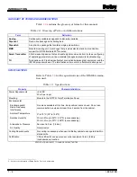
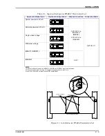
Table 2-2. NTAI05 Cable Applications
Nomenclature/Description
Application
Connector
Maximum Length
NKTU01 (PVC Jacket)
Connects NTAI05 to
IMASI02, IMFBS01, or
IMASM01
P1 on TU to MMU
backplane
61m
(200 ft)
NKTU11 (non-PVC Jacket)
DIPSHUNT RECEPTACLES
(XU9-XU16)
INPUT 16 NOT USED WITH
IMASI02 AND IMFBS01
DIPSHUNT RECEPTACLES
(XU1-XU8)
P1 CONNECTOR FOR
NKTU01/11 CABLE
DIPSHUNT RECEPTACLE
(XU17)
E2 (COMMON)
E1 (+24 VDC)
8
–
7
+
6
–
5
+
4
–
3
+
2
–
1
+
16
15
TB4
13
14
8
8
8
–
–
–
7
7
7
+
+
+
6
6
6
–
–
–
5
5
5
+
+
+
4
4
4
–
–
–
3
3
3
+
+
+
2
2
2
–
–
–
1
1
1
+
+
+
12
8
4
11
7
3
TB3
TB2
TB1
9
5
1
10
6
2
T00586A
9
8
10
7
15
2
14
3
13
4
12
5
11
6
16
1
XU16
9
8
10
7
15
2
14
3
13
4
12
5
11
6
16
1
XU12
9
9
8
8
10
10
7
7
15
15
2
2
14
14
3
3
13
13
4
4
12
12
5
5
11
11
6
6
16
16
1
1
XU8
XU4
9
8
10
7
15
2
14
3
13
4
12
5
11
6
16
1
XU15
9
8
10
7
15
2
14
3
13
4
12
5
11
6
16
1
XU11
9
9
8
8
10
10
7
7
15
15
2
2
14
14
3
3
13
13
4
4
12
12
5
5
11
11
6
6
16
16
1
1
XU7
XU3
9
8
10
7
15
2
14
3
13
4
12
5
11
6
16
1
XU14
9
8
10
7
15
2
14
3
13
4
12
5
11
6
16
1
XU10
9
9
8
8
10
10
7
7
15
15
2
2
14
14
3
3
13
13
4
4
12
12
5
5
11
11
6
6
16
16
1
1
XU6
XU2
9
8
10
7
15
2
14
3
13
4
12
5
11
6
16
1
XU13
9
8
10
7
15
2
14
3
13
4
12
5
11
6
16
1
XU9
9
9
8
8
10
10
7
7
15
15
2
2
14
14
3
3
13
13
4
4
12
12
5
5
11
11
6
6
16
16
1
1
XU5
XU1
XU17
9
8
10
7
15
2
14
3
13
4
12
5
11
6
16
1

