


16
16
ELECTRICAL
Power Specifications
Your machine is wired for 220 volts, 60hz alternating current. Before connecting the machine to
the power source, make sure the power source is OFF.
Before switching on the power, you must check the voltage and frequency of the power to see if
they meet with the requirement, the allowed range for the voltage is ±5%, and for the frequency
is ±1%.
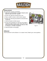
Considerations
•
Observe local electrical codes when connecting the machine.
•
The circuit should be protected with a time delay fuse or circuit breaker with a amperage
rating slightly higher than the full load current of machine.
•
A separate electrical circuit should be used for your machine. Before connecting the motor to
the power line, make sure the switch is in the “OFF” position and be sure that the electric
current is of the same characteristics as indicated on the machine.
•
All line connections should make good contact. Running on low voltage will damage the
motor.
•
In the event of a malfunction or breakdown, grounding provides a path of least resistance for
electric current to reduce the risk of electric shock. This machine is equipped with an electric
cord having an equipment-grounding conductor and a grounding plug. The plug must be
plugged into a matching outlet that is properly installed and grounded in accordance with all
local codes and ordinances.
CAUTION:
HAVE ELECTRICAL UTILITIES CONNECTED TO MACHINE BY
A CERTIFIED ELECTRICIAN!
Check if the available power supply is the same as listed on the machine nameplate.
WARNING:
Make sure the grounding wire (green) is properly connected
to avoid electric shock. DO NOT switch the position of the green grounding wire if
any electrical plug wires are switched during hookup.
WARNING:
In all cases, make certain the receptacle in question is
properly grounded. If you are not sure, have a qualified electrician check the
receptacle
.
Содержание IP-156
Страница 20: ...18 18 ELECTRICAL DIAGRAM...
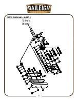
Страница 33: ...31 31 PARTS DIAGRAM SHEET 1 To Parts Sheet 2...
Страница 34: ...32 32 PARTS DIAGRAM SHEET 2 From Parts Sheet 1...
Страница 35: ...33 33 PARTS DIAGRAM SHEET 3...
Страница 36: ...34 34 PARTS DIAGRAM SHEET 4...
Страница 43: ...41 41 NOTES...


