23
23
PRESS FUNCTIONS
On /Off Switch
The On / Off switch is located on the front of the electrical panel on top of the hydraulic tank.
•
Turn the switch to the ON position to supply power to the electrical controls. The indicator
light on the electrical box will light up as long as the switch is ON.
•
Turn the switch to the OFF positon to remove power and stop the motor.
Direction Control Valve
The direction control valve is located on the right
side of the press frame.
The valve has 4 lever (A) positions labeled Fast
2, Slow 1, Stop 0, and Back R.
•
Stop 0 position: When the lever has not been
operated, the valve will always return to this
position. There is no movement of the piston.
•
Back R position: When the lever is pushed
inwards, the piston will raise. As long as the
valve is operated, the piston will move until it
is fully retracted. When the lever is released,
it will return to the stop 0 position and the
piston will stop and stay in the current
position.
•
Slow 1 position: When the lever is pulled
outwards to the first position, the piston will
extend at the working speed of .20”/sec (5mm/sec). As long
as the valve is held in this position, the piston will move
downward. When the lever is released, the piston will stop
and stay in this position. The lever will return to the stop
position. This positon will develop full pressure and should
be used during the actual pressing process.
•
Fast 2 position: When the lever is pulled outwards to the
second position, the piston will extend at the advancing
speed of .31”/sec (8mm/sec). As long as the valve is held in
this position, the piston will move. When the lever is
released, the piston will stop and stay in this position. The
lever will return to the stop position. This positon is for
advancing the ram to the material to be pressed. When the
ram is within .75” (19-20mm) the lever should be moved
back to the Slow 1 position to complete the operation.
B
A
Содержание HSP-176M-HD
Страница 3: ...ELECTRICAL SCHEMATIC 38 Electrical Parts List 38 TROUBLESHOOTING 39 ...
Страница 17: ...14 14 MODEL A B HSP 176M HD 57 08 1450mm 25 98 660mm HSP 176M 1500 HD 76 77 1950mm 25 98 660mm ...
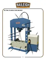
Страница 19: ...16 16 GETTING TO KNOW YOUR MACHINE A I G H L J B F K C E D ...
Страница 30: ...27 27 Using the Machine Incorrect Correct ...
Страница 31: ...28 28 Incorrect Correct ...
Страница 37: ...34 34 RAM PARTS DIAGRAM ...
Страница 39: ...36 36 HYDRAULIC PUMP PARTS DIAGRAM ...
Страница 43: ...40 40 NOTES ...


