18
18
Adjustments
Before making adjustments to
saw, push rocker switch to OFF. Also unplug saw
from power if working around blade area.
Arm Tilt
The table remains stationary, so the operator’s hands
can remain in the same comfortable position, with no
risk of the workpiece sliding off the table. The arm can
be tilted up to 45-degrees left or right for beveled cuts,
which are frequently used in projects such as
marquetry.
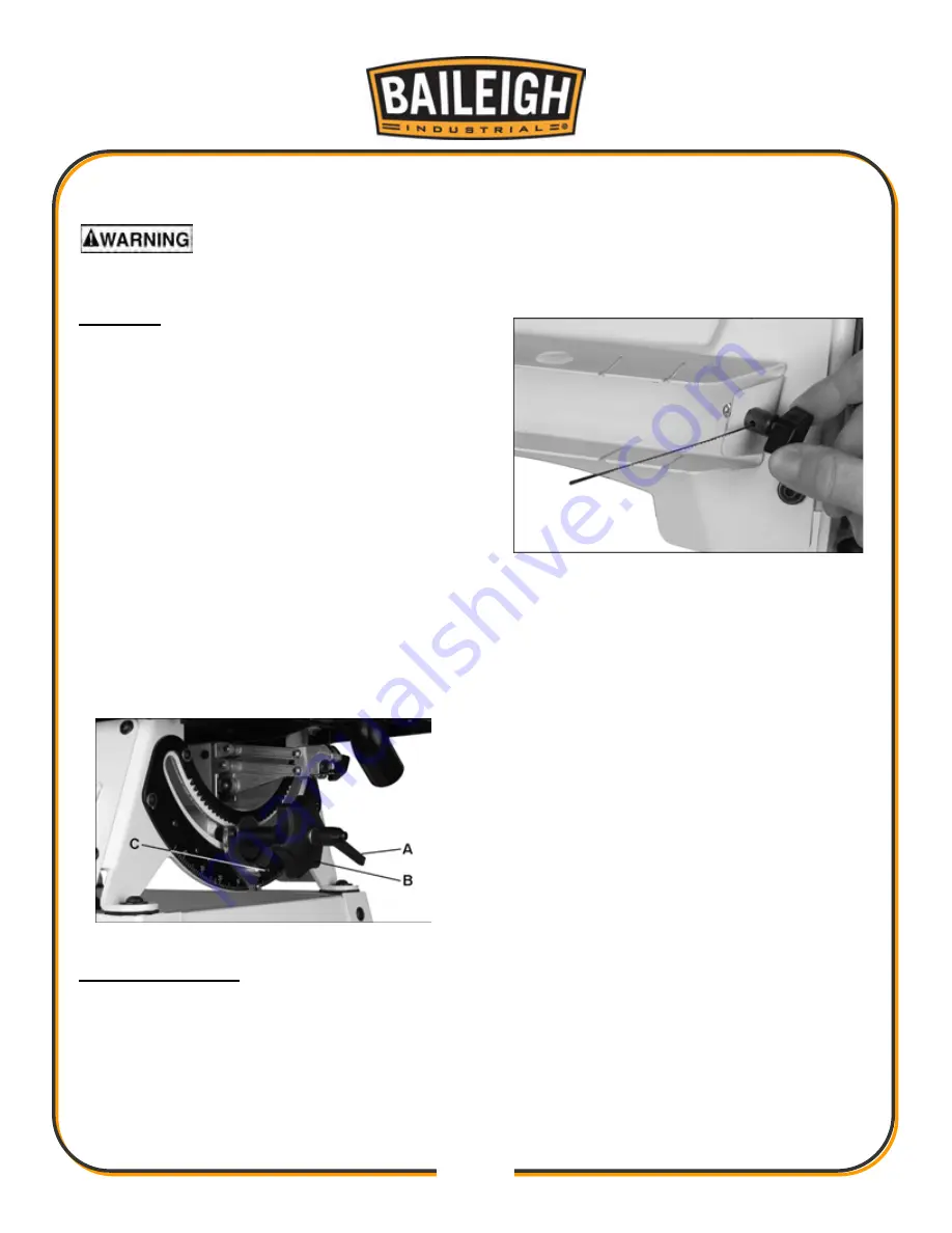
Refer to Figure 11.
1. Loosen lock handle (A).
2. Make sure upper guard and blower nozzle
positions will not conflict with table.
3. Rotate handle (B) to desired angle. Preset stops
are available at 90°, 45°, 30° and 22.5°, left and
right. Push detent pin (C) while rotating handle (B)
until pin engages hole.
4. Tighten lock handle (A) and release pin.
Lock handle (A) is adjustable to prevent obstruction
when in angled position: Pull out handle and rotate on
pin, then release, making sure it reseats on pin.
Figure 11: Arm Tilt Adjustment
Installing Blade
1. Turn off saw.
2. Insert lower blade holder (Figure 12) into hole in
blade rack for leverage and loosen knob.
3. Slide blade into holder deep enough to gain
sufficient clamping, but not all the way which can
result in blade being too short for sufficient
gripping by upper guide. Make sure blade teeth
point down, toward the blade holder. Tighten blade
holder knob.
NOTE: If the blade holder set screw is backed out,
turn it in with a 3mm hex wrench until it touches
the tip of the knob when knob is tightened down.
You may need to stabilize the blade holder with a
10mm wrench on the flats while doing this.
Figure 12: Installing Blade into Holder
4. Flip clamping lever (D, Figure 13) toward front of
saw to release guide.
5. Push blade holder into clip (E) while guiding blade
through table slot.
6. Push top end of blade into upper guide (F), making
sure it rests between the contact points of guide
set screws, and against the back stop.
7. Flip clamping lever (D) toward rear of saw to
tension blade.
Do not over-tension blade; this can
result in blade breakage or premature wear to
clamping surfaces.
Содержание BSS-22
Страница 13: ...13 13 Mounting Hole Pattern Figure 2 Scroll Saw Mounting Hole Pattern General Features Figure 3 BSS 22 Features...
Страница 30: ...30 30 BSS 22 Upper Lower Arm Assembly Exploded View...
Страница 32: ...32 32 BSS 22 Table Cabinet Assembly Exploded View...
Страница 34: ...34 34 BSS 22 Drive Link Assembly Exploded View...
Страница 37: ...37 37 Electrical Connections BSS 22 Scroll Saw...
Страница 38: ...38 38...
Страница 39: ...39 39...


