32
32
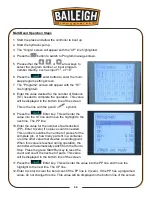
17. Press the
Enter key. This will enter the value into the CP line and move the
highlight to the next line. The XP line.
18. Place the Mode key switch in the semi-auto (right) position.
19. Press the
Start/Run key to enter the
operational page. This activates the system to allow
for operation.
a. The system will activate the setting that have
just been entered. This means that the Y and
X axis’s will move to the programmed
locations. Y will move first and then X.
b.
When the Y and X axis’s have finished
moving to the programmed positions, the
system is ready for a bend operation. If no
change was programmed into either the Y
and X axis’s, the system is ready for a bend
operation.
20. Place the work piece into the dies and up to the back-gauge.
21. Plan for the swing of the work piece during the bend.
a.
DO NOT
hold the work piece in an area that may become a pinch point.
b.
DO NOT
stand in an area that will strike the operator or bystanders during the bend
cycle.
22. When the die area and work piece swing area are clear, press and hold the Down foot pedal
to complete the bend.
a. The foot pedal may be released when the ram is lowered enough to engage the down
travel limit switch. If the foot pedal is released before the down travel limit switch is
engaged, the ram movement will stop. Press the Up pedal to lift the ram and start
again.
23. After a short pause based upon the HT time. The ram will raise back to the up position and
wait until the next bend command from the foot pedal.
24. A Single bend has been completed.
Содержание BP-3305CNC
Страница 3: ...Back Gauge Adjustment 48 BEND TONNAGE CHART 50...
Страница 17: ...14 14...
Страница 21: ...18 18 GETTING TO KNOW YOUR MACHINE A B M L K D C E F G I H J I G...
Страница 22: ...19 19 N S T U X V O Q P R W...
Страница 44: ...41 41 INCLUDED LOWER AND UPPER TOOLING Lower Tool Die Upper Tool Punch...
Страница 54: ...51 51 NOTES...
Страница 55: ...52 52 NOTES...


