


10 |
23
W. Baelz & Sohn GmbH & Co.
· Koepffstrasse 5 · 74076 Heilbronn · Germany ·
www.baelz.de Seite | Page
Straight-Tube Heat Exchanger baelz 111 / baelz 112
● For an accurate measurement of static pressure, select a location with steady flow. For the best
measurement conditions, arrange deburred holes of 3 to 5 mm diameter in straight pipelines and
perpendicular to the direction of flow. The distance to fittings or deflections should be at least 10 to 20
times the pipeline diameter.
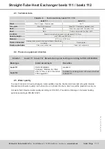
The performance and correct functioning of a heat exchanger system must be monitored by measuring pressure,
temperature and flow rate with sufficiently accurate measuring equipment. The data collected in this way is
indispensable for possible service cases. Baelz therefore recommends installing the following measuring
equipment in addition to the supply sensors and limit thermostats:
1. 1 thermometer each for steam inlet and condensate outlet.
2. 1 thermometer each for secondary inlet and secondary outlet.
3. 1 manometer each for steam inlet and condensate outlet.
4. 1 manometer each for secondary inlet and secondary outlet, or at least suitable measuring connection
piece for the later connection of a manometer.
5.
1 condensate meter, or at least one fitting piece for a condensate meter, so that a temporary meter for
maximum quantity setting can be installed during initial commissioning.
6.
1 warm or hot water meter or one measuring orifice for the secondary circuit.
The necessary calming section must be available for all quantity measuring devices.
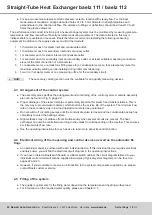
4.3 Arrangement of the control system
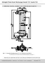
● The assembly plan specifies the arrangement and functioning of the control system. A sample assembly
plan can be found in Fig. 5, page 20.
●
Proper drainage of the steam inlet pipe is particularly important for steam heat transfer stations. This is
the only way to prevent water hammer, which shortens the service life of the system. The minimum flow
rate on the secondary side in low load operation must also be guaranteed.
●
Do not switch off circulating pumps until the condensate valve is closed and the condensate backup has
completely covered the heating surface.
●
Night setbacks may not all take effect simultaneously when several circuits are present. The heat
exchanger can also be controlled according to the coldest circuit depending on the weather. This ensures
a minimum water flow rate.
●
See the operating instructions for each device to learn more about its control function.
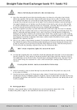
4.4
Electrical wiring of the measuring and control devices as well as the automatic fit
-
tings
●
An operating manual is enclosed with each individual device. If this individual device requires electrical
auxiliary power, you will find the electrical circuit diagram in the operating instructions.
●
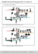
If you have ordered a Baelz switchboard or a Baelz switch cabinet, the circuit diagram tailored to your
individual control circuit will also be supplied. Examples of typical system diagrams can be found on
pages 22 and 23.
●
However, if you would like to receive an introduction to the system components supplied by us, please
contact Baelz customer service.
4.5 Filling of the system
● The quality requirements for the filling water depend on the temperature and heating surface load.
●
For information on the required water quality, please see Chapter 2.5
Info:


