


4
dispense order is received by the meter.
QT
.
QT
..
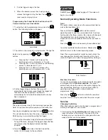
RF Mode
1. Press
on meter to receive dispense order
from keypad: Trigger unlocks.
QT
.
..
RF Mode Batch
2. Pull the trigger to begin the flow. The valve will
automatically lock in place, even though the trigger
will fall back to the closed position. The flow will
automatically shut off when the programmed
dispense order size has been dispensed.
Do
NOT
press
before topping off. The meter will
return to a lock-out position and not allow additional fluid
to be dispensed until receipt of a valid dispense order
from this keypad.
3. The user has the option to top off at the end of the
dispense order. To top off the tank, simply pull the
trigger to begin the flow and release when the
desired amount has been pumped.
4. Press the
button when finished to reset the
meter. This total quantity dispensed will be
transmitted to the keypad and the meter will return
to a lock-out position. The meter is now ready to
receive the next dispense order from the keypad.
Manual Mode - No RF Communications
1. Program the meter to manual mode by holding
down TOTAL key and pressing
,
,
,
and AUTO. The solenoid will now unlock and the
meter may be used as a standard Auto Series EPM.
QT
.
QT
..
Manual Mode
5.
Slowly open the dispense valve and allow enough oil
to pass through to ensure that the system is clean.
Close the valve and repeat for all dispense positions.
Note: If the system has multiple dispense positions, begin
at the position farthest from the pump, and move
towards the pump.
6.
Relieve the Pressure
(see Relieve the System
Pressure, above).
7.
Insert the metal end of the hose into the swivel
located at the end of the handle, and tighten
completely with an open ended, adjustable wrench.
Attaching the hose
Note: The threaded end of the meter will always have
female threads, so the metal end of the hose must
have male threads. Apply thread sealant to the male
end. The inlet and outlet connections are both 1/2"
NPT or 1/2" BSPP depending on meter model.
8.
Thread the new nozzle onto the opposite end of the
meter and screw in tightly with an open ended,
adjustable wrench.
Installing the nozzle
9.
Open all dispense position shut-off valves, and start
the pump to pressurize the system.
10. To ensure accuracy, purge all air from the fluid lines
and dispense valve before use.
Operating the Meter - Manual Mode -
When RF Communications are
Unavailable
Operating the Meter
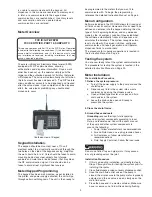
RF Mode:
When the battery pack is attached to the meter, the meter
will automatically enter the RF Mode. The trigger is in a
lock-out position and no oil can be dispensed until a


