background image

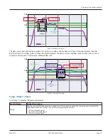
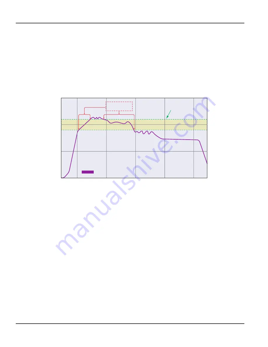
For example, if the average flow rate is 100 gpm and the 

Hysteresis

 is set to 10%, a filter window of 90…110 gpm is 

established  Successive flow measurements that reside within that window are recorded and averaged in accordance with the 

Damping

 setting  Flow readings outside of the window are rejected or accepted in accordance with the  

Bad Data Rejection

 setting 

Filter settings for this example:

Filter Method

Adaptive

Damping

40 seconds

Sensitivity

60%

Hysteresis

10%

Bad Data Rejection

3

Flow Within

Hysteresis Limit

±10% Hysteresis

Limit

Flow

150

100

50

0

110

90

Figure 27:  Hysteresis window

Bad Data Rejection (Range 0…10 Samples; Default: 3)

The 

Bad Data Rejection

 setting is related to the number of successive 

readings

 that must be measured outside of a the 

Hysteresis

 value before the flow meter considers the new flow value valid  In this example, a 

Hysteresis

 setting of 10% produces 

a ± 10% band centered on the current valid flow rate of 100 gpm 
The 

Bad Data Rejection

 setting is the number of successive 

samples

 that must be outside of the 

Hysteresis

 window before 

the flow meter considers the change in flow as real  Larger values are entered into the 

Bad Data Rejection

 window when 

measuring liquids that contain gas bubbles, as the gas bubbles tend to disturb the ultrasonic signals and cause more 

extraneous flow readings to occur  Larger 

Bad Data Rejection

 values tend to make the flow meter less responsive to rapid 

changes in actual flow rate 
I

Figure 29 on page 23

,


flow data falls outside the flow 

Hysteresis

 window but does not reach the minimum time specified in 

the 

Bad Data Rejection

 window  When data appears that is outside the 

Hysteresis

 band and shorter than the 

Bad Data Rejection


window time, the data is rejected  

Parameter Descriptions by Menu

Page 22 

May 2021

TTM-UM-02537-EN-06

Содержание Dynasonics TFX-500w

Страница 1: ...Transit Time Ultrasonic Flow Meters TFX 500w Clamp On Meter TTM UM 02537 EN 06 May 2021 User Manual ...

Страница 2: ...Transit Time Ultrasonic Flow Meters TFX 500w Clamp On Meter Page ii May 2021 TTM UM 02537 EN 06 ...

Страница 3: ...siderations 9 Equipment Required 9 Installing the Transducers 9 Installing a Meter with a Remote Transmitter and Fixed Transducers 10 Installing a Meter with a Remote Transmitter and Adjustable Transducers 11 Installing a Meter with an Integral Transmitter 12 Wiring the Transmitter 13 Wiring the Transducer 13 Initial Meter Setup 16 Menu Map 17 Parameter Descriptions by Menu 18 Main Menu Structure ...

Страница 4: ...ification Messages 32 Error Messages 32 Check Function Codes 32 Warning and Alarm Message Codes 33 Symptoms 35 Replacement Instructions 36 Front Panel Replacement 36 Main Board Replacement 36 Specifications 38 System 38 Transmitter 38 Transducers 39 Configuration Software 39 Part Number Construction 40 North American Pipe Schedules 42 Parts and Accessories 44 Couplant 44 Power Supplies 44 Transit ...

Страница 5: ... for equipment damage in transit is the sole responsibility of the purchaser SAFETY Mounting electrical installation start up and maintenance of the instrument may only be carried out by trained personnel authorized by the operator of the facility Personnel must read and understand this User Manual before carrying out its instructions Terminology and Symbols WARNING Indicates a hazardous situation...

Страница 6: ...requency modulated burst of sound energy between the two transducers The burst is first transmitted in the direction of fluid flow and then against fluid flow Sound energy in a moving liquid is carried faster when it travels in the direction of fluid flow downstream than it does when it travels against fluid flow upstream The sound s time is accurately measured in both directions Figure 1 Meter op...

Страница 7: ...sor bar highlights the submenu or parameter that will be viewed or edited The scroll bar on the right indicates the relative position the cursor bar is at on the list when there are more than 4 items MENU BACK returns to parent menu up a level If at the Main top level menu returns to the Home Screen DOWN ARROW scrolls the list RIGHT ARROW and ENTER have the same function in the menu structure and ...

Страница 8: ...how the item is selected MENU BACK exits parameter editing and returns to the parent menu up a level Entering a Number The parameter name and current value is displayed in the top portion of the screen Edit the number on the bottom right of the screen MENU BACK exits parameter editing and returns to parent menu up a level The parameter remains at the value displayed in the top portion of the scree...

Страница 9: ...plete the meter programming Installation Considerations Mount the transmitter in a location Where little vibration exists That is protected from corrosive fluids That is within the transmitters ambient temperature limits With display 4 140 F 20 60 C without display 40 158 F 40 70 C That is out of direct sunlight Direct sunlight may increase transmitter temperature to above the maximum limit Equipm...

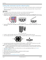
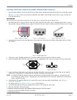
Страница 10: ...apter plate 4 If necessary rotate the adapter plate by 90 to accommodate the final orientation of the transmitter 5 Mount the adapter plate either to a wall with 4 customer supplied 8 or M4 screws or to a pipe with mounting straps Holes for Screws Holes for Screws Holes for Straps Figure 7 Wall mount Figure 8 Pipe Mount 6 Use conduit holes where cables enter the enclosure from the bottom Use plugs...

Страница 11: ...ntation of the transmitter 4 Mount the adapter plate either to a wall with 4 customer supplied 8 or M4 screws or to a pipe with mounting straps Holes for Screws Holes for Screws Holes for Straps Figure 13 Wall mount Figure 14 Pipe Mount 5 Use conduit holes where cables enter the enclosure from the bottom Use plugs to seal any holes that are not used for cable entry A cable gland kit is included fo...

Страница 12: ...and reinstalling all of the connections 4 Use conduit holes where cables enter the enclosure from the bottom Use plugs to seal any holes that are not used for cable entry A cable gland kit is included for inserting the transducer and power cables OTE N Use NEMA 4 IP 66 rated fittings plugs to maintain the watertight integrity of the enclosure Generally the right conduit hole viewed from front is u...

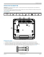
Страница 13: ...UT 1 2 9 28V DC 5W Max TB300 Transducer Connector TB400 Power Connector TB600 Output Connector TB500 Digital I O Connector Figure 17 Wiring connectors Wiring the Transducer 1 Guide the transducer terminations through the transmitter conduit hole in the bottom left of the enclosure 2 Secure the transducer cable with the supplied conduit nut if flexible conduit was ordered with the transducer 3 The ...

Страница 14: ...V DC In power ground and chassis ground as in Figure 19 OTE N DC powered transmitters are protected from major catastrophe with an internal 1 5 Amp SLO BLO fuse If this fuse is blown the transmitter must be inspected and the fuse replaced at the factory IMPORTANT A Class II DC power supply is required Power 9 28V DC Power Common Chassis Ground Switch or Circuit Breaker 1 2 3 TB400 External Equipme...

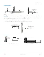
Страница 15: ...e cable network to be independently accessed Either Modbus RTU or BACnet MS TP protocol is used to interrogate the transmitters Flow rate and total can be monitored over the digital communications bus When a USB programming cable is connected the RS485 and frequency outputs are disabled TB600 External Equipment 5 6 RS485 RS485 A B 60 4 Ohms 60 4 Ohms Terminator Resistors Enabled through Parameter ...

Страница 16: ...based on whether MANUAL INCHES or MANUAL MM was selected for the Pipe Type LINER THICKNESS and LINER MATERIAL optional If there is a liner in the pipe enter the liner thickness and select the liner material The units are based on the Pipe Type If you do not see a valid option check the Pipe Type I D SIZE The calculated inner diameter based on settings TRANSDUCER DTTN DTTR 1 MHZ DTTSU 2 MHZ DTTS DT...

Страница 17: ...tatus Total Overflow Count Passcode Level Clear History Factory Reset Reboot O Reset Flow Total Unlatch Alarms Units Meter Input Output S Transducer Mounting Pipe Spacing Flow Setup Shunt Calibration S Current Output Output 1 Output 2 Input Press to toggle the options Press to access this menu Press to select a main menu option S Network Type Settings Endpoint Communications A Passcode Recovery Te...

Страница 18: ...GAL MIN Gallons Minute L MIN Liters Minute GAL H Gallons Hour L H Liters Hour MG D Million Gallons Day M3 S Cubic Meters Second IG S Imperial Gallons Second M3 MIN Cubic Meters Minute IG MIN Imperial Gallons Minute M3 H Cubic Meters Hour IG H Imperial Gallons Hour FT3 S Cubic Feet Minute BBL MIN Barrel Minute FT3 MIN Cubic Feet Minute MIG D Million Imperial Gallons Day FT3 H Cubic Feet Hour BBL D ...

Страница 19: ...e TFX 500w meter DTTJ K EASYRAIL 1 MHZ Options JZ and KZ when ordered with the TFX 500w meter DTTN DTTR 1 MHZ Options NZ WZ and RZ when ordered with the TFX 500w meter MOUNTING For mounting options see the transducer user manual Z PATH V PATH W PATH DTTS DTTC TYPE DTTS DTTC TYPE is substituted for MOUNTING when TRANSDUCER DTTS DTTC is selected as the transducer type CA 1 2 IN ANSI CJ 1 1 4 IN COPP...

Страница 20: ... selected the following classes are also available CLASS A CLASS E CLASS B CLASS F CLASS C CLASS G CLASS D CLASS H If ductile iron pipe material is selected the following classes are also available CLASS 50 CLASS 54 CLASS 51 CLASS 55 CLASS 52 CLASS 56 CLASS 53 If aluminum or brass naval material enter the pipe size in inches PIPE SIZE Available only when PIPE TYPE is MANUAL Numeric entry min 0 5 i...

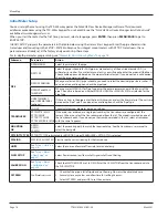
Страница 21: ...ers Simple with Rejection uses Damping and Bad Data Rejection to filter the flow data Adaptive filtering allows the meter s software routines to alter the filtering depending on the variability of the transducer s signal The Adaptive filter uses a combination of Damping Bad Data Rejection Sensitivity and Hysteresis to modify the flow input data Damping Range 0 100 Seconds Default 40 Seconds Dampin...

Страница 22: ...onsiders the new flow value valid In this example a Hysteresis setting of 10 produces a 10 band centered on the current valid flow rate of 100 gpm The Bad Data Rejection setting is the number of successive samples that must be outside of the Hysteresis window before the flow meter considers the change in flow as real Larger values are entered into the Bad Data Rejection window when measuring liqui...

Страница 23: ...the new established flow rate New 10 Hysteresis Limit Old 10 Hysteresis Limit Bad Data Rejection Window 150 100 50 0 110 90 Flow 1 2 3 4 4 Samples Outside Hysteresis Limit Flow Outside Original Hysteresis Limit Figure 29 New valid flow data Setup Meter Shunt An asterisk indicates the parameter default Shunt Submenu Options Descriptions SHUNT Changing the SHUNT attenuates the received wave If the s...

Страница 24: ...after entering the CAL FACTOR Set Zero Procedure SET ZERO removes the No Flow transit time offset This is also referred to as Zeroing the meter Because every flow meter installation is slightly different and sound waves can travel in slightly different ways through these various installations it is important to remove the zero offset at zero flow to maintain the meter s accuracy To establish Zero ...

Страница 25: ...es based on parameter selected Negative numbers accepted MAX VALUE Enter the value of the reading at 20 mA Units and decimal places based on parameter selected Negative numbers accepted TEST CURRENT Available only when OUTPUT SOURCE is in TEST MODE Default 12 00 mA To check the wiring to the control system or gauge you can override the current output with a fixed current Numeric entry mA 0 22 mA T...

Страница 26: ... Frequency 2000 Hz With this setup at no flow the frequency output is 1000 Hz MAX VALUE Numeric entry Units based on source selected Negative numbers accepted Default 5000 MAX FREQUENCY Numeric entry Units in Hz Default 1 kHz TEST FREQUENCY Available when TEST MODE is selected for OUTPUT SOURCE To check the wiring to the control system or device you can override the frequency output with a fixed f...

Страница 27: ...an in order to trigger an alarm SET LOW is only visible settable when ALARM is set to LOW FLOW OUT OF RANGE or ALL LATCHING DISABLED ENABLED When ENABLED the output remains on after the alarm condition clears Resetting alarm latch turns off the output ANTI CHATTER SET DELAY Enter how long the alarm condition must occur before activating the output to prevent nuisance trips Numeric entry Default is...

Страница 28: ...ter to match the Modbus RTU master TIMEOUT DISABLE Numeric entry 0 10000 ms Enter 0 ms to disable the timeout option For networks with a predictable poll rate by the master device this parameter is an option to record and display an S60 code when the meter does not receive a message from the master device Enter the time that the meter should record and display a loss of communication timeout BACNE...

Страница 29: ... display returns to the Home Screen Passcode Recovery Only the ADMIN level can reset passcodes If the ADMIN passcode is lost and the passcodes need to be reset you can contact Badger Meter provide a recovery code to the representative and request a temporary passcode To generate a recovery code 1 Select PASSCODE RECOVERY 2 The next screen prompts you to generate a recovery code or cancel the reque...

Страница 30: ... to reduce the display BRIGHTNESS after the buttons are not pressed for the TIMEOUT period Select the BRIGHTNESS level Default is 10 Press any button to awaken the transmitter and return to normal BRIGHTNESS The buttons pressed will not be active for one second after the transmitter is awakened DIMMER LEVEL NUMERIC 0 100 TIMEOUT 5 MINUTES 10 MINUTES 20 MINUTES 30 MINUTES 60 MINUTES Information Men...

Страница 31: ... HISTORY buffer This is typically done after startup or maintenance on the flow system is successfully completed FACTORY RESET FACTORY RESET confirmation screen Resets all parameters to the values on the device when it was shipped from the factory Any settings made will be reset REBOOT REBOOT confirmation screen Reboots the device The TFX 500w meter does not require this manual REBOOT for any proc...

Страница 32: ...nd description If conditions cause multiple messages to occur all messages will be saved to the history but some messages may not be displayed If an error condition occurs warning and alarm messages will not be displayed If multiple errors occur each error message will cycle through and be viewable for 5 seconds Similarly if multiple warning or alarm conditions occur but no error conditions each m...

Страница 33: ...mproper programming incorrect parameter values Improper transducer spacing Non homogeneous pipe wall To test the meter off the flow system you can cap a short section pipe and fill with it with water Then set up and test the meter Although no flow will occur there should be a signal F11 HIGH SIGNAL Signal strength is oversaturated Change transducer mounting from V mount to W mount or Z mount to V ...

Страница 34: ...check SET HIGH parameter If flow rate does not appear to be correct follow the actions for symptom Flow reading appears to be incorrect S45 LOW FLOW S46 LOW FLOW Flow rate is below low flow alarm setting for output 1 S45 or output 2 S46 in transmitter Check flow rate displayed on transmitter If flow rate appears to be correct and alarm should not be triggered check SET LOW parameter of the output ...

Страница 35: ...T on the top of the pipe Check that the transducers are NOT located at the highest point in the loop where air may accumulate Check that the transducers are NOT on a downward flowing pipe unless adequate downstream head pressure is present to overcome partial filling or cavitation Check that the transducers have adequate straight pipe upstream and downstream Check process loop for entrained air or...

Страница 36: ...oard PN D020 2100 005 if necessary Instructions follow CONTAINS PARTS AND ASSEMBLIES SUSCEPTIBLE TO DAMAGE BY ELECTROSTATIC DISCHARGE ESD BEFORE PICKING UP AN ESD SENSITIVE ELECTRONIC COMPONENT DISCHARGE YOURSELF BY TOUCHING A GROUNDED BARE METAL SURFACE OR APPROVED ANTI STATIC MAT OBSERVE PRECAUTIONS FOR HANDLING ELECTROSTATIC SENSITIVE DEVICES Tools Required A Philips 2 screwdriver A flat blade ...

Страница 37: ...move the display board as doing so will damage the display To install the main board 1 While holding the main board insert the keypad ribbon cable into the keypad ribbon cable connector at J501 You may need to use tweezers for electronics to insert the ribbon cable Slide the cable retainer toward the center of the board to secure the keypad ribbon cable 2 Align the pins on the display board to the...

Страница 38: ... Feet Day Liters Second Liters Minute Liters Hour Cubic Meters Second Cubic Meters Minute Cubic Meters Hour Cubic Feet Minute Cubic Feet Minute Cubic Feet Hour Gallons Second Gallons Minute Gallons Hour Million Gallons Day Imperial Gallons Second Imperial Gallons Minute Imperial Gallons Hour Barrel Minute Million Imperial Gallons Day Barrel Day Mounting Wall or pipe remote mount or integral mount ...

Страница 39: ...ass filled Ultem Nylon cord grip PVC cable jacket 40 250 F 40 121 C 100 ft 30 m max 2 5 6 in DN65 DN150 2 5 10 in DN65 DN250 NEMA 6 IP67 DTTC integral mount temperature is limited by the transmitter temperature rating Configuration Software The flow meter can be programmed and configured with the SoloCUE Flow Device Manager software The software also has troubleshooting tools for diagnosing and co...

Страница 40: ...0 ft 9 14 m AF 50 ft 15 24 m AK 75 ft 22 86 m AR 100 ft 30 48 m BW CONDUIT TYPE AND LENGTH 1 None WW 15 ft 4 57 m AC 30 ft 9 14 m AF 50 ft 15 24 m AK 75 ft 22 86 m AR 100 ft 30 48 m BW RESERVED Standard XX UNITS OF MEASURE TOTALIZER FLOW RATE Gallons gallons per minute G Gallons cubic feet per minute B Cubic Meters cubic meters per minute T Cubic Meters cubic meters per hour H Cubic Feet gallons p...

Страница 41: ...2 86 m AR 100 ft 30 48 m BW 150 ft 45 72 m BK 200 ft 60 96 m DW 250 ft 76 20 m DK 300 ft 91 44 m EW RESERVED Standard XX UNITS OF MEASURE TOTALIZER FLOW RATE Gallons gallons per minute G Gallons cubic feet per minute B Cubic Meters cubic meters per minute T Cubic Meters cubic meters per hour H Cubic Feet gallons per minute F Cubic Feet cubic feet per minute J Liters liters per second N Liters lite...

Страница 42: ...teel stainless steel PVC pipe standard classes Steel Stainless Steel PVC Pipe Standard Classes continued NPS in OD in SCH 5 SCH 10 Lt Wall SCH 20 SCH 30 STD SCH 40 ID in Wall in ID in Wall in ID in Wall in ID in Wall in ID in Wall in ID in Wall in 1 1 315 1 185 0 065 1 097 0 109 1 049 1 049 0 133 1 25 1 660 1 53 0 065 1 442 0 109 1 380 1 380 0 140 1 5 1 900 1 77 0 065 1 682 0 109 1 610 1 610 0 145...

Страница 43: ...0 063 ID 0 995 1 025 1 055 1 062 ID 4 805 4 875 4 907 5 063 4 874 1 25 OD 1 375 1 375 1 375 1 660 6 OD 6 125 6 125 6 125 6 625 6 000 Wall 0 065 0 055 0 042 0 146 Wall 0 192 0 140 0 122 0 250 0 063 ID 1 245 1 265 1 291 1 368 ID 5 741 5 845 5 881 6 125 5 874 1 5 OD 1 625 1 625 1 625 1 900 7 OD 7 625 7 000 Wall 0 072 0 060 0 049 0 150 Wall 0 282 0 078 ID 1 481 1 505 1 527 1 600 ID 7 062 6 844 2 OD 2 ...

Страница 44: ...scription D002 2011 001 Dow Corning Molykote 111 Grease 5 3 oz Tube 150 F 65 C D002 2011 002 Dow Corning 732 Permanent Mount 356 F 180 C Dow 111 grease is included with transducers Power Supplies Part Number Description 68334 001 Wall Plug 100 264V AC In 24V DC Out 20 50 C 68334 002 Module 85 264V AC In 24V DC Out 30 70 C For ordering transducers and transmitter separately please contact factory T...

Отзывы: