background image

Unpacking the PDU

n

Unpack the delivery and check its completeness and integrity If

there is a defect, contact Bachmann GmbH immediately.

n

If possible, keep the packaging of the PDU so that the PDU

can be safely stored and transferred in the future. Dispose of

the packaging material that is no longer required in a manner

that is environmentally responsible.

Unpacking

Unpacking the PDU

25.09.2015

BlueNet PDU BN3000/3500/5000/7000/7500

15

Содержание BlueNet BN3000

Страница 1: ...BlueNet PDU BN3000 3500 5000 7000 7500 Assembly and installation instructions Read the instructions prior to performing any task ...

Страница 2: ...nstraße 33 70565 Stuttgart Germany Telephone 49 711 86602 0 Fax 49 711 86602 34 email bluenet bachmann com Internet www bachmann com Bach 30131 DE 5 en_GB Bachmann GmbH 2015 25 09 2015 BlueNet PDU BN3000 3500 5000 7000 7500 2 ...

Страница 3: ... copyright Their use is permitted in conjunction with the assembly and installation of the PDU Any use that exceeds this is not permitted unless the written approval of Bachmann GmbH has been obtained The software contains components that are protected by copyright and are licensed in terms of various license models A copy of the terms of the licenses is included with the PDU as of software ver si...

Страница 4: ...Installation with plug in brackets via the sides of the PDU 20 5 3 5 Installation with the mounting solution in the rack 21 5 4 Connecting the PDU to the power supply 23 5 5 Connecting the network cable 23 5 6 Connecting the sensors 24 5 7 Cascading the PDUs 24 6 Putting the PDU into operation 27 6 1 Adjusting the display orientation 27 6 2 Querying the network address of the PDU 28 6 3 Configurin...

Страница 5: ... Connector panel for network Modbus and sensors D Control panel E Fitting slots for plug in bracket Fig 2 Product overview 32 amp version A CEE connector plug B Sockets C Circuit breaker automatic fuse D Connector panel for network Modbus and sensors E Control panel F Fitting slots for plug in bracket Overview of functions Example of a 16 amp version Example of a 32 amp version Overview Overview o...

Страница 6: ... S1 to connect a sensor via a cat 5e cable B Modbus port M1 to connect a master PDU and upstream slave PDUs via a cat 5e cable C Modbus port M2 to connect a slave PDU via a cat 5e cable D Sensor port S2 to connect a sensor via a cat 5e cable Connector panel for a master PDU Fig 3 Connector panel master PDU Connector panel for a slave PDU Fig 4 Connector panel slave PDU Overview Overview of the PDU...

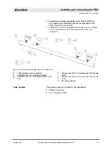
Страница 7: ... A Fitting slots for plug in bracket B Attachment for the mounting bracket C Attachment for the mounting solution in the rack D Plug in bracket for mounting the PDU via the back 2 each E Plug in bracket for mounting the PDU via the sides 2 each F Mounting bracket x 2 Control panel Fitting options on the back Overview Overview of the PDU 25 09 2015 BlueNet PDU BN3000 3500 5000 7000 7500 7 ...

Страница 8: ...via SNMP access or with a web browser over a network and the HTTP HTTPS SSH SNMP and Modbus TCP protocols can be used The PDU is made of a sturdy aluminium profile and is installed directly into the rack Depending on the type the PDU has a variety of features such as safety plug sockets or IEC320 C14 and C20 type non heating appliance connectors and external sensors temperature humidity A connecto...

Страница 9: ...is issuing an alarm based on all the measurements of the master PDUs and sensors or the signal to a slave PDU or a sensor has been interrupted Yellow Continuously yellow PDU is starting up White Continuously white Light signal to release the pressed key during Factory Reset Purple 500 ms off 500 ms purple An update of a PDU is being car ried out Purple red 500 ms off 500 ms purple 500 ms off 500 m...

Страница 10: ...t yet estab lished or lost Green red 500 ms off 100 ms green 500 ms off 100 ms red Connection to master PDU present internal communication problems have occurred Green 900 ms off 100 ms green Connection to master PDU present internal communication functioning Purple 500 ms off 500 ms purple An update of the internal modules of a PDU is being carried out Purple red 500 ms off 500 ms purple 500 ms o...

Страница 11: ...nnected to each other via the Modbus port This way up to 10 slave PDUs can be cascaded with a master PDU and managed via the web interface The slave PDU is connected to the master PDU via the M1 Modbus port Further slave PDUs are connected to each other via the M1 M2 Modbus ports of the particular slave PDU The PDU can be integrated into the network via the LAN port The data transfer rate is contr...

Страница 12: ...C19 Fig 12 Ⓔ The plug in bracket for mounting the PDU via the sides is included in the delivery as of August 2015 1 6 Optional accessories The temperature and humidity at the installation location of the PDU can be measured via a temperature sensor and a humidity sensor The values can be displayed in the display and on the web interface The cat 5e cable required to connect the sensors is included ...

Страница 13: ...ation of symbol and signal word indicates that there is a potential danger that can result in damage to property if it is not avoided This symbol highlights useful tips and recommenda tions as well as information for efficient and trouble free operation The following markings are used to highlight specific instructions results lists references and other elements in these instructions Marking Expla...

Страница 14: ... IT systems and have a basic knowledge of electrical engineering Due to their specialist training IT specialists are in a position to assess the consequences of their actions in dealing with the system as well as its components and the potential dangers in respect thereof and are able to avoid these The duties of an IT specialist include the following tasks n Setting up hardware and software syste...

Страница 15: ...nn GmbH immediately n If possible keep the packaging of the PDU so that the PDU can be safely stored and transferred in the future Dispose of the packaging material that is no longer required in a manner that is environmentally responsible Unpacking Unpacking the PDU 25 09 2015 BlueNet PDU BN3000 3500 5000 7000 7500 15 ...

Страница 16: ... con ditions set out in the technical specifications n The the PDU may not be used in potentially explosive atmos pheres n The PDU may not be subjected to vibrations n A location for the installation must be selected that does not have excessive humidity high temperatures sources of elec tromagnetic interference moisture solvents flammable gases dust or vapours n There must be sufficient lighting ...

Страница 17: ...itting options for the PDU A Fitting slots for plug in bracket B Attachment for the mounting bracket C Attachment for the mounting solution in the rack D Plug in brackets for mounting the PDU via the back E Plug in brackets for mounting the PDU via the sides F Mounting bracket The following tools are required for the installation n Phillips screwdriver n Torx screwdriver IP8 Tools required Install...

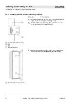
Страница 18: ...gainst the rack and mark the position of the mounting holes 3 Remove the mounting brackets Fig 15 Ⓐ from the PDU and screw them onto the rack in the positions marked Fig 14 Installation with mounting brackets A PDU B Mounting bracket Fig 15 Rack with mounting brackets Installing and connecting the PDU Installing the PDU Installing the PDU with the mounting brackets 25 09 2015 BlueNet PDU BN3000 35...

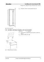
Страница 19: ...ecialist 1 Insert the plug in brackets into the rear slots on both sides Fig 17 2 Position the PDU in the rack Fig 16 Rack with PDU Fig 17 Fitting the plug in brackets Installing and connecting the PDU Installing the PDU Installation with plug in brackets via the rear of the PDU 25 09 2015 BlueNet PDU BN3000 3500 5000 7000 7500 19 ...

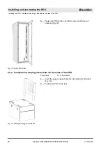
Страница 20: ...onnel n IT specialist 1 Insert the plug in brackets into the side slots on both sides Fig 19 2 Position the PDU in the rack Fig 18 Rack with PDU Fig 19 Fitting the plug in brackets Installing and connecting the PDU Installing the PDU Installation with plug in brackets via the sides of the PDU 25 09 2015 BlueNet PDU BN3000 3500 5000 7000 7500 20 ...

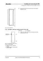
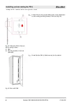
Страница 21: ...nt for the mounting bracket with a screwdriver Fig 21 Ⓐ Fig 20 Rack with PDU Fig 21 Unscrewing the attachment for the mounting bracket A Attachment for the mounting bracket B Attachment for the mounting solu tion in the rack Installing and connecting the PDU Installing the PDU Installation with the mounting solution in the rack 25 09 2015 BlueNet PDU BN3000 3500 5000 7000 7500 21 ...

Страница 22: ...hat the PDU is fitted securely into the cabinet Fig 22 Fitting the PDU in the rack with mounting solution A PDU B Mounting solution in the rack example Fig 23 Rack with PDU Installing and connecting the PDU Installing the PDU Installation with the mounting solution in the rack 25 09 2015 BlueNet PDU BN3000 3500 5000 7000 7500 22 ...

Страница 23: ...mains completely unplug its power cable from the power socket Do not touch the power cable plug with wet hands When unplugging the power cable plug from the power socket always pull the plug and not the cable Do not pull the cable to unplug the power cable plug The power cable must not be crushed kinked damaged by sharp edges or subjected to any other mechanical stress Avoid subjecting the power c...

Страница 24: ... Several PDUs can be connected to each other via the Modbus port This way up to 10 slave PDUs can be cascaded with a master PDU and managed via the web interface It is not possible to connect individual PDUs with a crossover cable Personnel n IT specialist 1 Connect a cat 5e cable to the Modbus port M1 of the master PDU 2 Connect a cat 5e cable to the Modbus port M1 of the slave PDU 3 Connect furt...

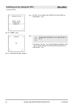
Страница 25: ...o open the Settings menu 4 Use the key to select the Modbus Config menu and con firm by pressing the key Setting the Modbus address on the slave PDU Fig 27 BlueNet menu Fig 28 System menu Fig 29 Settings menu Installing and connecting the PDU Cascading the PDUs 25 09 2015 BlueNet PDU BN3000 3500 5000 7000 7500 25 ...

Страница 26: ...igned from 1 to 16 If necessary use the key to switch between digits Use the key to set the address for the slave PDU and confirm by pressing the key Fig 30 ADDR menu Fig 31 Setting the Modbus address Installing and connecting the PDU Cascading the PDUs 25 09 2015 BlueNet PDU BN3000 3500 5000 7000 7500 26 ...

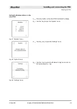
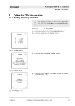
Страница 27: ...ialist 1 Press any button on the PDU to activate the display 2 Use the key to open the System menu 3 Use the key to open the Settings menu 4 Use the key to select the Orientation menu and confirm by pressing the key Fig 32 BlueNet menu Fig 33 System menu Fig 34 Settings menu Putting the PDU into operation Adjusting the display orientation 25 09 2015 BlueNet PDU BN3000 3500 5000 7000 7500 27 ...

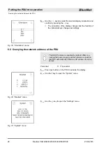
Страница 28: ...ault After con necting the power supply and the network connection the PDU automatically obtains an IP address from the server Personnel n IT specialist 1 Press any button on the PDU to activate the display 2 Use the key to open the System menu 3 Use the key to open the Settings menu Fig 35 Orientation menu Fig 36 BlueNet menu Fig 37 System menu Putting the PDU into operation Querying the network ...

Страница 29: ... XX The PDU is configured for the web interface with the setup wizard In certain windows the navigation buttons Skip or Back are available The respective browser button to go back has no function in this application For a detailed description of the web interface see Ä Chapter 7 Operation on page 39 Personnel n IT specialist 1 Select the IP address of the PDU https IP address in a web browser ð Th...

Страница 30: ...tup wizard Fig 42 Ⓐ or skip setup Fig 42 Ⓒ Use the Start setup wizard button Fig 42 Ⓐ to start the setup wizard ð The Network settings window opens The network settings can be set automati cally via the DHCP protocol or entered man ually in the setup wizard Logging in Fig 40 Login Fig 41 Opening the setup wizard Fig 42 BlueNet 2 Web UI window Putting the PDU into operation Configuring the PDU via ...

Страница 31: ... Network settings window click the Manual setup button Fig 45 Ⓐ ð The Network configuration window opens Using the network settings via DHCP Fig 43 Network settings window Fig 44 DHCP information window Configuring the network settings manually Fig 45 Network settings window Putting the PDU into operation Configuring the PDU via the web interface software version V1 00 XX 25 09 2015 BlueNet PDU BN...

Страница 32: ...select the DHCP on parameter in the DHCPv6 option menu Fig 46 Ⓓ Alternatively select the Manual parameter and manually enter the IPv6 address IPv6 prefix length and gateway 12 Confirm the entries by clicking the Continue button Fig 46 Ⓔ 13 In the SNMP settings window enter the location Fig 47Ⓐ and the contact Fig 47 Ⓑ 14 If required click the Activate SNMP V1 2 checkbox Fig 47 Ⓒ 15 If required cli...

Страница 33: ...inue button Fig 49 Ⓒ 24 If required click the Activate NTP checkbox Fig 50 Ⓐ enter a server address Fig 50 Ⓑ and select a time zone Fig 50 Ⓒ Alternatively do not click the Activate NTP checkbox Fig 50 Ⓐ and only enter the date and time Fig 50 Ⓓ 25 Confirm the entries by clicking the Continue button Fig 50 Ⓔ 26 Use the Finish button Fig 51 Ⓐ to close the setup wizard Fig 48 IP addresses window Conf...

Страница 34: ...menu you can start the setup wizard Fig 53 Ⓐ or skip setup Fig 53 Ⓒ Use the Start setup wizard button Fig 53 Ⓐ to start the setup wizard ð The Network settings window opens The network settings can be set automati cally via the DHCP protocol or entered man ually in the setup wizard 4 In the Network settings window click the Use DHCP button Fig 54 Ⓐ ð The DHCP information window opens Logging in Fi...

Страница 35: ...ions menu in the Network settings window acti vate the DHCPv4 checkbox in the IPv4 area Fig 57 Ⓐ Alternatively do not activate the DHCPv4 checkbox and enter the IP address subnet mask and gateway manually Fig 55 DHCP information window Configuring the network settings manually Fig 56 Network settings window Putting the PDU into operation Configuring the PDU via the web interface as of software ver...

Страница 36: ...Fig 57 Ⓔ 11 If necessary enter a gateway in the IPv6 area Fig 57 Ⓕ 12 If necessary activate the Stateless autoconfig checkbox in the IPv6 area Fig 57Ⓖ 13 Confirm the entries by clicking the Continue button Fig 57 Ⓗ 14 In the SNMP settings window enter the location Fig 58Ⓐ and the contact Fig 58 Ⓑ 15 If required click the Activate SNMP V1 2 checkbox Fig 58 Ⓒ 16 If required click the Activate SNMP V...

Страница 37: ... Fig 60 Ⓒ 25 If required click the Activate NTP checkbox Fig 61 Ⓐ enter a server address Fig 61 Ⓑ in the Server 1 field and select a time zone Fig 61 Ⓒ If necessary enter additional server addresses in the Server 2 Fig 61 Ⓒ and Server 3 Fig 61 Ⓓ fields Alternatively do not click the Activate NTP checkbox Fig 61 Ⓐ and only enter the date and time Fig 61 Ⓕ 26 Confirm the entries by clicking the Cont...

Страница 38: ...Ⓐ to close the setup wizard Completing the setup wizard Fig 62 Setup window Putting the PDU into operation Configuring the PDU via the web interface as of software version V1 01 XX 25 09 2015 BlueNet PDU BN3000 3500 5000 7000 7500 38 ...

Страница 39: ... instructions for your software version of the PDU You can read the software version on the PDU Ä Reading the software version on page 39 Personnel n IT specialist 1 Press any button on the PDU to activate the display 2 Use the key to open the System menu 3 View SW to read the software version of the PDU Reading the software version Fig 63 BlueNet menu Fig 64 System menu Operation 25 09 2015 BlueN...

Страница 40: ...r supply The PDU is not connected correctly n Check the connections The status LED does not light up There is no voltage n Check the fuses if any n Connect the on site power supply The PDU is not connected correctly n Check the connections No current at one socket There is no voltage n Check the fuses if any n Connect the on site power supply Troubleshooting 25 09 2015 BlueNet PDU BN3000 3500 5000...

Страница 41: ...k of damage to the PDU due to improper cleaning Cleaning that is carried out improperly can damage the PDU Do not use strong acids or bases for cleaning Only clean the PDU with a lint free cloth Do not use a high pressure cleaner or compressed air for cleaning Keep splashing and sprayed water away from the PDU Electric current Improper cleaning Cleaning the PDU 25 09 2015 BlueNet PDU BN3000 3500 5...

Страница 42: ...sconnect the CEE plug from the power supply 2 Unplug the power cable plug 3 Unplug the plugs of the connected devices 4 Dismantle the PDU from the rack 10 2 Disposal Electric and electronic components must not be disposed of with household waste If the service life of the PDU has expired dispose of it according to the applicable local waste disposal regulations Never use force to open the PDU Elec...

Страница 43: ...he housing of the PDU and contains the following information n Product name n Part number n Serial number n MAC address physical network address n Rated current n Rated voltage n Power frequency n Manufacturer s address n CE marking Specifications of the PDU Nameplate Technical specifications 25 09 2015 BlueNet PDU BN3000 3500 5000 7000 7500 43 ...

Страница 44: ... of the PDU 19 with plug in brackets via the sides of the PDU 20 with the mounting bracket 18 with the mounting solution in the rack 21 Installation location 16 L Login 29 M Modbus LED 7 11 Mounting bracket 7 12 16 N Nameplate 43 Network cable 23 Non heating appliance locking device 12 O Operation 39 P Personnel 14 Plug in bracket 7 12 16 Product overview 5 Putting into operation Adjusting the dis...

Отзывы: