Instruction 3015-4275
73
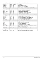
Zone Data
Register 0x12xxh R/W 78 bytes
Each zone for an AGM300 has a separate Zone data structure that is 78 bytes long. The zone number is the
low order byte in the register address (i.e., Zone 1 data register = 0x1201h)
Variable Type
Length
Description
Location
C
13 bytes
13 byte array, Alpha Numeric Description or Name of Zone
Flow OK
UC
1 byte
Status of Flow check. Value of 1 indicates flow check is
good.
DO NOT MODIFY
Refrig. Type
UC
1 byte
See note 1 Below (DEFAULT = R134a)
Distance
UI
2 bytes
Zone Tubing Length (in feet) (DEFAULT = 100 feet)
Zone Temp
I
2 bytes
Avg temp at zone (degrees C) (DEFAULT = 25
°
C)
Concentration
Float
4 bytes
Last Measured concentrations (uM/L)
DO NOT MODIFY
Concentration2
Float
4 bytes
Last Measured concentration (PPM)
DO NOT MODIFY
Alarm Ack
UC
1 bytes
Set value to 1 to acknowledge Alarm.
NOTE:
AGM300 will
reset this byte to 0 when the Alarm byte (below) is = 0 and
zone in alarm is sampled. If the alarm condition/byte
increases (leak>>spill or spill>>evac) the AGM300 will also
reset this byte to 0
Alarm
UC
1 bytes
Alarm Status; 0 = no alarm, 1 = leak; 2 = spill; 3 =
evac.
Leak Level
UI
2 bytes
Level to trigger a leak alarm (in PPM) (DEFAULT = 100)
Spill Level
UI
2 bytes
Level to trigger a spill alarm (in PPM) (DEFAULT = 300)
Evac Level
UI
2 bytes
Level to trigger a evacuate alarm (in PPM) (DEFAULT =
500)
Peak PPM
UI
2 bytes
Highest Recorded PPM in zone
Peak Time
TIM
13 bytes
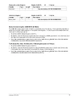
Date an time of highest peak (see note 2 for format)
Alarm Time
TIM
13 bytes
Date and time of last alarm (see note 2 for format)
Not Used
13 bytes
Log Interval
UI
2 bytes
Number of minutes between Log entries (DEFAULT =
1440)
NOTE 1:
Refrigerant Types Defined from 00h to 20h in the following order : 00h=R11, 01h=R12, 02h=R22,
03h=R23, 04h=R113, 05h=R114, 06h=R123, 07h=R124, 08h=R134a, 09h=R401a, 0Ah=R402a, 0Bh=R402b,
0Ch=R404a, 0Dh=R407a, 0Eh=R407c, 0Fh=R409a, 10h=R410a, 11h=R500, 12h=R502, 13h=R503,
14h=R507, 15h=R508b, 16h=H1301, 17h=R408a, 18h=Future2, 19h=Future3, 1Ah=Future4, 1Bh=Future5,
1Ch=Future6, 1Dh=Future7, 1Eh=New1, 1Fh=New2, 20h=New3
NOTE 2:
Time Structure Format consists of 13 unsigned character types. They are 1 second digit, 10 second
digit, 1 minute digit, 10 minute digit, 1 hour digit, 10 hour digit, 1 day digit, 10 day digit, 1 month digit, 10 month
digit, 1 year digit, 10 year digit, last byte is unused.
Содержание ADM800
Страница 17: ...Instruction 3015 4275 9 AGM300 AC Input Power and Ground Connections...
Страница 33: ...Instruction 3015 4275 25 ADM800 AC Input Power and Ground Connections...
Страница 70: ...62 Instruction 3015 4275 Notes...
Страница 71: ...Instruction 3015 4275 63 Appendix...
Страница 74: ...66 Instruction 3015 4275 ADM800 Logic Diagram...
Страница 93: ...Instruction 3015 4256 85 Notes...


