Instruction 3015-4275
69
Notes on Network Topologies
AGM300s may be connected directly to the MODBUS network or they may be connected to the network
through an ADM800. In either case, each AGM300 must have a unique node ID. Up to 15 AGM300s can be
connected directly to the MODBUS network.
If AGM300s are accessed via an ADM800 connected to a MODBUS network, the ADM800 “BMS enabled”
parameter must be set equal to “1” via the “ADM SETUP” screen on the ADM800. The same commands and
registers are used to communicate with the AGM300 directly or through the ADM800. If the communications is
through the ADM800, it monitors each MODBUS message to determine if the message is intended for one of
the AGM300s it is connected to. If it is, the ADM800 passes the message through to the AGM300s. If it is not,
the message is not passed through. The ADM800 does not make any modifications to MODBUS messages. It
simply passes the query through to the AGM300, and passes the response back to the MODBUS master. In
other words, it allows the AGM300s to be logically connected to the MODBUS network, when physically they
are connected to the local ADM800 network. It is very important to understand that the ADM800 will only pass
messages through to the AGM300 when the ADM800 is either in the “SYSTEM” screen or the “ZONE VIEW”
screen. If the ADM800 is in any other screen, it will return a MODBUS “busy” exception response (exception
code 06).
All ADM800 screens except the SYSTEM and ZONE VIEW screens have a 10 minute timeout interval, after
which the screen will return to either the SYSTEM or ZONE VIEW screen, depending on which one it was last
in. Also, the ADM800 can be password protected such that a password entry is required in order to view
screens other than the SYSTEM or ZONE VIEW screen.
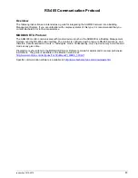
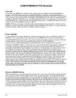
Key Comm Protocol Parameters
MODBUS Mode:
RTU only
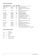
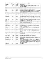
AGM300 Baud Rate:
Default is 19,200. Programmable as defined in System data register
Parity:
No Parity
Stop Bits:
Default is 1. Can be set for 2 via System data register
Maximum Response Time:
4000mS when directly accessing the AGM300. 8,000mS when accessing the
AGM300 through the ADM800.
Error Checking:
CRC per MODBUS specifications
Also of note is the fact that all data sent out from the AGM-300 is in “little endian” byte order (Least significant
byte followed by most significant byte). This should be taken into account if the master that process the data is
a “big endian” type. Non-data information (starting address, number of points, etc.) follows normal MODBUS
protocol, which is Big Endian.
Содержание ADM800
Страница 17: ...Instruction 3015 4275 9 AGM300 AC Input Power and Ground Connections...
Страница 33: ...Instruction 3015 4275 25 ADM800 AC Input Power and Ground Connections...
Страница 70: ...62 Instruction 3015 4275 Notes...
Страница 71: ...Instruction 3015 4275 63 Appendix...
Страница 74: ...66 Instruction 3015 4275 ADM800 Logic Diagram...
Страница 93: ...Instruction 3015 4256 85 Notes...

