6
5
Copyright © 2022, Baby Trend Inc., All Rights Reserved. Todos los derechos reservados.
Copyright © 2022, Baby Trend Inc., All Rights Reserved. Todos los derechos reservados.
ASSEMBLY ASAMBLEA
ASSEMBLY ASAMBLEA
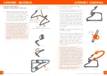
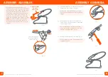
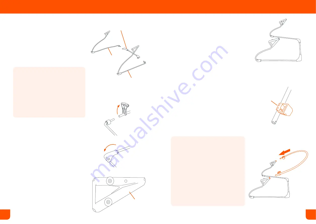
BOUNCER FRAME ASSEMBLY
MONTAJE DEL ARMAZÓN DEL REBOTADOR
Fig. 1a
Fig. 1b
Fig. 1c
Rear base frame tube
Tubo posterior del armazón
de la base
Left Base Frame Wire
Alambre izquierdo del
armazón de la base
Right Base Frame Wire
Alambre derecho del armazón de la base
1)
• Place the rear base frame tube on a flat
surface (Fig. 1a) and lift the plastic corners
(Fig. 1b). Insert the left and right base
frame wires into the rear base frame tube.
Push the plastic corners back down until
they snap securely onto the base frame
wires (Fig. 1c). Set the assembled Base
frame aside and proceed to step 2.
• Coloque el tubo del armazón de la base
trasera sobre una superficie plana (Fig.
1a) y levante las esquinas de plástico.
(Fig. 1b) Introduzca los alambres derecho
e izquierdo del armazón de la base en
el tubo del armazón de la base trasera.
Empuje la s esquinas de plástico hacia
atrás y abajo hasta que se fijen bien a
presión en los alambres del armazón de la
base (Fig. 1c). Deje a un lado la estructura
de la base ensamblada y proceda con el
paso 2.
A
B
Diagram
Diagrama
C
2)
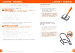
• Reference the 3-Way Connector Diagram
below for Steps 2
and 3.
• Use de referencia el Diagrama del Conector
de 3 Vías a continuación para los pasos 2 y 3.
• The 3-Way Connectors will be preassembled
at corner A (Fig 2a). Place the Base frame
upright on a flat surface with corners B and
C of the 3-Way Connectors pointing up (Fig.
2b). The Backrest Bar has 2 square brackets
with an opening for the Toy Bar. Be sure that
the openings are facing up (Fig 2b). Align the
Backrest bar to corner B. Insert both ends
into the 3-Way connector until they click into
place (Fig 2c).
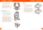
•
DO NOT
Discard the Foam Padding from the
Footrest Wire (Fig 2d).
• To Insert the Footrest Wire, align the ends to
corner C of the 3-Way Connector.Be sure the
small curvature parallels with the surface and
the ends of the wire both point up (Fig 2d).
Insert the ends into the 3-Way Connectors
and be sure that they click into place.
NOTE:
The pins on the 2 Bars must click into
position when inserted into the connectors
correctly (Fig. 2e).
• Los conectores de 3 vías estarán
ensamblados previamente en la esquina A
(Fig 2a). Coloque la estructura de la base en
posición vertical sobre una superficie plana
con las esquinas B y C de los conectores de 3
vías apuntando hacia arriba (Fig 2b). La barra
del respaldo tiene 2 abrazaderas cuadradas
con una abertura para la Barra de Juguetes.
Asegúrese de que las aberturas apunten
hacia arriba (Fig 2b). Se debe alinear la barra
del respaldo con la esquina B. Inserte ambos
extremos en el conector de 3 vías hasta que
hagan clic al llegar a su lugar (Fig 2c).
•
NO
quite la almohadilla de espuma del
alambre del apoyapiés (Fig 2d).
Fig. 2c
Fig. 2b
Fig. 2a
Facing up
Hacia arriba
B
B
A
C


