Optima OS600L
Instructions for Use
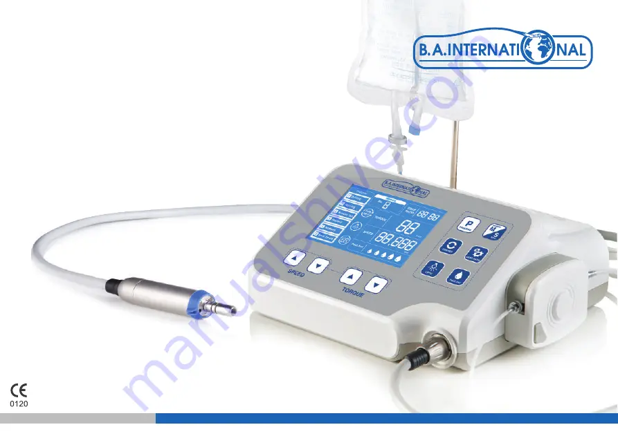
Implant and Surgical Unit BA160510 / 9795068 / ISE-270M
EN 2-15p / ES 16~30p / FR 31~45p / IT 46~60p / NL 61~75p / DE 76~90p
language
Страница 1: ...Optima OS600L Instructions for Use Implant and Surgical Unit BA160510 9795068 ISE 270M EN 2 15p ES 16 30p FR 31 45p IT 46 60p NL 61 75p DE 76 90p language ...
Страница 2: ...ance Chapter 7 Troubleshooting Chapter 8 Accessories and Service Chapter 9 Product Disposal Guideline Annex A 1 Catalog number Serial number Manufacturer Authorized representative in the European Community Manufacturing Date BF type applied part Alternating current Keep dry Caution Consult operating instructions Do not dispose with domestic waste Water proof grade Distributor IPX1 Implant and Surg...
Страница 3: ...res and some fixed type 6 Where the patient requires implant support in relation to the lower dentures to maintain the full denture and also improve its function 1 5 Checklist Prior to Use 1 Be sure to read the user manual prior to use 2 Only to be used by a professional in a professional environment 3 Not to be used for anything other than its intended use Chapter 2 Safety Warnings and Cautions 2...
Страница 4: ...the device 9 Ensure that the main body of the implant engine and the foot pedal do not come in contact with water saline solution or other contaminants If the device is not operating properly or contaminants have entered the product do not operate the device under any circumstances and inquire with the manufacturer instead 10 Please use the device in accordance with the use stated in this user man...
Страница 5: ...button Program button Memory button Gear ratio button Coolant button Optic LED button Speed Up Down button Torque Up Down button Water injection pipe fixture Motor connection 3 1 2 Foot switch BA160535 Foot switch connector Foot switch coable Rotation button Program button Coolant button Hanger hole Operation button 3 1 3 Motor BA160530 Optic LED Motor connection Handpiece connection 4 ...
Страница 6: ... 2 250 T2 0AH 300 230 135 Width Length Height 3 Foot Switch BA160535 Speed control Control Functions Control Functions Variable Program control Coolant control Forward Reverse IPX1 3 4 Environmental Conditions Storage Relocation Operation 1 Storage conditions Temperature 10 C 50 C Humidity 10 85 Air pressure 500hPa 1060hPa 2 Relocation conditions Temperature 10 C 50 C Humidity 10 85 Air pressure 5...
Страница 7: ...r Insert foot switch hanger into hanger hole Fix by connecting hanger bolt 4 2 Connection of Motor Plug the motor connector flush into the groove Connect the motor connector CAP Be careful when plugging in the connector 4 3 Connection of power cord and foot switch Connect power cable to power cable terminal Connect Foot switch connector to Foot switch terminal Be careful to fit into the groove upo...
Страница 8: ...rrigation tube Coolant clip Y tube Attach the irrigation tube to the straight or contra angle handpiece Irrigation tube Push button Connect irrigation cover and Irrigation tube Tube clamp Coolant container Insert needle Open Irrigation cover by pressing Push button Put Irrigation tube in the groove Close Irrigation cover Close the tube clamp Open the tube clamp before start up Stick the insert nee...
Страница 9: ...g Foot switch It rotates at low speed with light press on Foot switch and rotates at full speed with hard press When the irrigation flow rate is preset the pump starts rotating as well 5 When load reaches the maximum value of preset torque motor stops rotating 6 It stops rotating upon releasing Foot switch 7 Turn off the implant engine controller Connect the engine to the power cable Turn the engi...
Страница 10: ...apping program Program Button 5 2 2 Thread cutting function Program Button Foward rotation Foward rotation when foot sweetch is on Rotation stop when foot sweetch is released Reverse rotation when loading beyond the preset torque limit value 5 2 3 Deleting a program This function deletes unnecessary and unused programs Select an unused program and delete it by pressing this button for more than 2 ...
Страница 11: ...5 3 2 Saving data Memory Button Memory 1 Drilling set value Tapping set value Remove tap set value Implant set value Remove set value Rock screw set value Memory 9 Drilling set value Tapping set value Remove tap set value Implant set value Remove set value Rock screw set value Save detailed figures in memory which are currently set Gear ratio Torque Speed For Rev Coolant for each function in progr...
Страница 12: ...tton Optic LED Button Press Optic Non optic button to operate LED within the motor BA160530 which is designed for Optic It selects gear ratio in accordance with that on a handpiece Gear ratio alters upon pressing Gear ratio button each time When the LED is on the LED symbol is displayed During the motor operation LED is on When motor stops the LED turns off after 3 seconds When the LED is off the ...
Страница 13: ...80 000 16 1 12 2 500 20 1 10 2 000 27 1 7 1481 32 1 6 1250 5 10 Operation of implant engine 5 11 Auto Calibration SPEED Up Down Button Implant engine operates upon completion of all settings When motor operates by pressing foot switch the letter R on display and the surrounding border flickers in turn The torque and speed indicate the current figures and a beep sounds when altered torque value rea...
Страница 14: ...he motor cable from controller 2 Attach the motor cap to the handpiece connection of the motor 3 Sterilize the motor equipped with the cap and motor cable either before or after use under the following conditions Sterilization by moist heat 134 135 for 3 minutes in a steam sterilizer Autoclave Clean the product before and after use Please sterilize after using the product We do not recommend you t...
Страница 15: ...temperature sensor Restart after turning off the power then leave unit on standby E5 Transformer error Defective transformer overheating Contact your BA repair centre E6 Error on circuit and voltage Defective circuit Contact your BA repair centre E7 Error on pedal connection Poor pedal connection Reconnecting and checking the pedal Error number E1 E8 will pop up and keep flashing depending on each...
Страница 16: ...160543 Foot switch hanger BA160544 Irrigation tube BA690110 Hanger bolt BA160546 Tube holder BA160545 Stand BA160548 Instruction for use Motor cap for autoclave BA160547 15 Chapter 9 Disposal 10 1 Disposal guideline 10 1 1 Disposal of Main controller and foot switch and motor Follow your country specific laws directives standards and guidelines for the disposal of used electrical devices Ensure th...
Страница 17: ...rge ESD IEC61000 4 2 IEC 60601 Level Compliance Level 6kV contact 8kV air 6kV contact 8kV air 6kV contact 8kV air 6kV contact 8kV air 6kV contact 8kV air 6kV contact 8kV air Surge IEC61000 4 5 Electromagnetic Environment Guidance Floor should be wood concrete or ceramic tile If floors are covered with synthetic material the relative humidity should be at least 30 Mains power quality should be that...
Страница 18: ...people and animals Rated maximum output power of transmitter in watts W Separation distance according to the frequency of transmitter in meter m 150 kHz to 80 MHz d 1 2 P 80 MHz to 800 MHz d 1 2 P 800 MHz to 2 5 GHz d 2 3 P 3 Vrms 150 kHz to 80 MHz 3 Vrms Conducted RF IEC 61000 4 6 3V m 80 MHz to 2 5 GHz 3 Vrms Radiated RF IEC 61000 4 3 for 800 MHz to 2 5 GHz where P is the maximum output power ra...
Страница 19: ......
Страница 20: ...arl Marx Str 6 16540 Hohen Neuendorf Germany Contact 49 0 3303 5412323 Fax 49 0 3303 5412324 Manufacturer MicroNX co Ltd MicroNX co branch office Address 22 Maeyeo ro 1 gil Dong gu Daegu 41059 Republic of Korea Contact 82 53 650 1000 micronx micronx co kr www micronx co kr Made in Republic of Korea The EU directive 93 42 EEC was applied in the design and production of this medical device 04 2019 ...