background image

PT-6IL


MAINBOARD


HARDWARE  SETUP

22

Pin assignment of keyboard connector

Pin #  Signal name

Pin #  Signal name

Pin #  Signal name

   1

Keyboard Data

   3

Ground

   5

Keyboard Clock

   2

No Connection

   4

+  5V DC

   6

No Connection

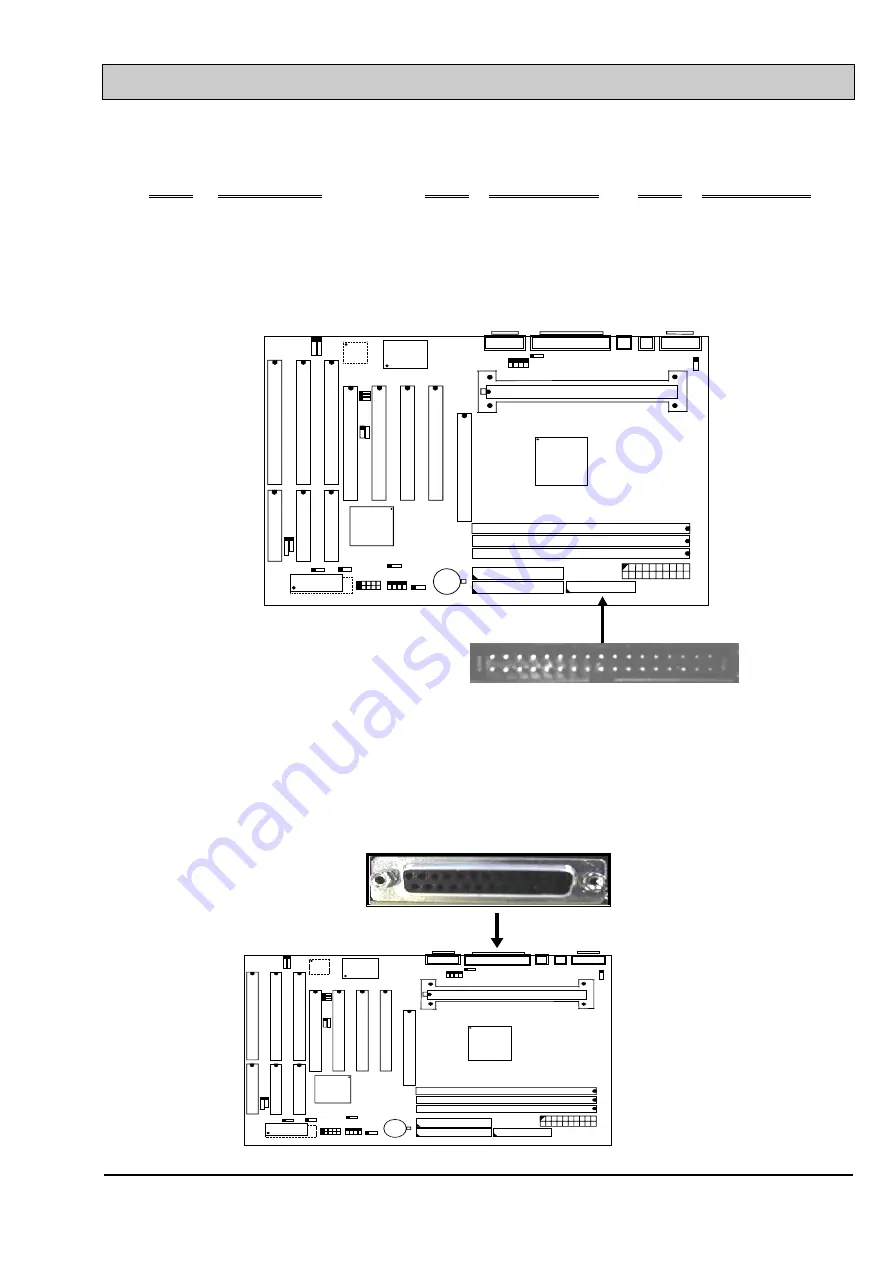
(G) CN6: Floppy Disk Control Port Connector (Using IRQ6, DMA channel 2)

CN 2

US

B2

US

B1

BAT1

+

_

SLOT1

SPKR

A

G

P

 S

L

O

T

IS

A

 S

L

O

T

IS

A

 S

L

O

T

IS

A

 S

L

O

T

PC
I S
L

O

T

PC
I S
L

O

T

PC
I S
L

O

T

PC
I S
L

O

T

CN 11

CN7

CN5

CN4

CN9 IDE 2
CN10 IDE 1

CN6 FDC

CN3

BIOS

KBLOCK CN 12

CN 1

J 1

CN 6

FLOPPY DISK CONNECTOR

(H) CN7: Parallel  Port  Connector

(Supports SPP/EPP/ECP modes, IRQ7 or IRQ5 is selectable, ECP mode will use
either DMA channel 3 or channel 1 which can be selected by the CMOS setup
probram)

US

B

2US

B

1

B A T 1

+

_

S L O T 1

S P K R

A

G

P

 S

L

O

T

IS

A S
L

O

T

IS

A S
L

O

T

IS

A S
L

O

T

PC
I S

L

O

T

PC
I S

L

O

T

PC
I S

L

O

T

PC
I S

L

O

T

C N   1 1

C N   2

C N 7

C N 5 C N 4

C N 9   ID E   2
C N 1 0   ID E   1

C N 6   F D C

C N 3

B IO S

K B L O C K C N   1 2

C N   1

J 1

P a r a llel  P o r t

C N   7

Содержание 6IL

Страница 1: ...PT 6IL MAINBOARD VER 1 x USER S MANUAL ...

Страница 2: ...NISM KIT 5 3 4 INSTALL THE BOXED PENTIUM II PROCESSOR 6 3 5 REMOVING BOXED PENTIUM II PROCESSOR 10 3 6 INSTALLING OEM PENTIUM II PROCESSOR 12 3 7 REMOVING OEM PENTIUM II PROCESSOR 14 3 8 INSTALLING DRAM 14 3 9 CONNECTORS 18 3 10JUMPERS 33 4 AWARD BIOS SETUP 4 1 4 1 GETTING STARTED 1 4 2 MAIN MENU 2 4 3 CONTROL KEYS 2 4 4 STANDARD CMOS SETUP 3 4 5 BIOS FEATURES SETUP 4 4 6 CHIPSET FEATURES SETUP 6 ...

Страница 3: ...age connected to the ATX form factor mainboard Without disconnecting the AC power connector from the PC system the mainboard may be damaged by any incorrect action Please refer to the page 4 16 for executing procedures WAKE ON LAN In order to support the Wake On LAN feature the system requires a special SPS switching power supply Such power supply must be able to provide at least 700 mA of driving...

Страница 4: ...order execution etc In order to optimize of its capabilities and performances the 32 bit Operating System such as Windows NT and OS 2 and 32 bit application are recommended The Accelerated Graphics Port A G P on the PT 6IL mainboard is designed for AGP 3D video display card Unlike PCI based display cards the AGP technology provides lightning data throughput to fully facilitate the 3 Dimensional an...

Страница 5: ...3977TF SL3 USB2 USB1 SL2 SL1 PCI 1 PCI 2 PCI 3 JP3 JP2 CN3 POWER CON CN15 CN16 CN11 COM B CN2 COM A CN4 PS 2 MS PS 2 KB CN1 DIMM 3 CN8 CN5 CN7 LPT CN9 IDE2 CN10 IDE1 CN6 FDC JP9 BAT1 PCI 4 AGP _ DIMM 2 DIMM 1 CN12 JP5 CN17 IR FIR CIR CN13 SB LINK 82443LX intel JP1 JP4 SLOT1 J1 J2 CN14 JP8 JP7 JP6 LM78 LM79 SYS BIOS ...

Страница 6: ...e Simply plug in the CPU and start immediately WORD SIZE Data Path 8 bit 16 bit 32 bit 64 bit Address Path 32 bit PC SYSTEM CHIPSET Intel 82440LX AGPset 82443LX 82371AB SUPER I O CHIPSET Winbond W83977TF W83977ATF optional BUS FREQUENCY 66 MHz fixed MEMORY DRAM Three 168 pin DIMM sockets are designed onboard which support 8 16 32 64 or 128MB 3 3V Un buffered EDO and SDRAM DIMM modules Maximum memo...

Страница 7: ...ial Bus USB ports 5 pin for each port IDE PORTS Two channels of Ultra DMA 33 Bus Master IDE ports which will support up to 4 IDE devices like IDE hard disk ATAPI CD ROM and LS 120 ZIP 100 devices The IDE ports can be programmed to support PIO Mode 4 DMA mode 2 and Ultra DMA 33 SUPER I O PORTS 1 Two high speed NS16C550 compatible serial ports UARTs 2 One parallel port supports SPP EPP ECP mode 3 On...

Страница 8: ... power on the system by panel switch Keyboard PS 2 Mouse Modem ring in RTC alarm or LAN signal 2 Power off soft off by OS or Panel switch 3 CPU cooling fan auto off during Suspend state 4 Resuming of PC system such as Modem ring in RTC alarm etc 5 Supports Full On Doze Standby Suspend operating modes JUMPER FREE In order to provide a most convenient way to help users to install the CPU onto the ma...

Страница 9: ...sealed in the original packing until when installing A grounded anti static mat is recommended when unpacking and installation Please also attached an anti static wristband to your wrist and have it grounded to the same point as the anti static mat After the opening of the mainboard carton please observe the mainboard carefully to make sure there is no shipping and handling damage before you can i...

Страница 10: ...hout the correct password or hot key no one else can turn on the PC system neither by the power button So the PC system is secured for you There are two ways to power on the PC system by keyboard they are Password and Hot KEY Please refer to page 4 11 for the BIOS setting When the Password and Hot KEY is selected you will have to reboot the PC system to activate the setting when you see the POST P...

Страница 11: ...n the RTC memory When RTC alarms the PC system will be triggered and wakes up automatically Enable the Resume by Alarm selection in the BIOS setup utility and then input the accurate date and time in following fields the Resume by Alarm is located in the POWER MANAGEMENT SETUP please refer to page 4 8 and page 4 9 for detail procedures Having stored the RTC alarm setting the PC system will be turn...

Страница 12: ... setup you have to reboot the PC system so that BIOS can verify the setting the DMI pool data will be verified by the BIOS when loading the operating system Simply speaking shut down the PC system and reboot the system The modem ring in feature will be enabled when the operation system has been loaded Note This function is unavailable when using the internal MODEM card WAKE ON LAN WOL There is a W...

Страница 13: ... verify the DMI pool data A POWER OFF THE PC SYSTEM There are two ways to power off the system They are Shut Down by Power Button please refer to page 3 28 for details and Shut Down by OS such as Windows 95 and Windows 98 you can choose the Shut Down from the file menu and the system will be powered off immidiately ...

Страница 14: ...esigned for Pentium II processor and we call it the SLOT 1 Basically Slot 1 is a new technology and it is totally different to the traditional Pentium CPU socket Socket 7 Because Slot 1 is a revolutionary new architecture and the installation of Pentium II processor need some additional skill The following sections will show you how to install the CPU support kit and install the Pentium II process...

Страница 15: ...cal The major difference between these two processors is the boxed CPU has head sink cooling fan and heat sink supporter while the OEM Pentium II CPU doesn t Please look at following pictures for the difference 1 Boxed Pentium II CPU Boxed Pentium CPU Boxed Pentium CPU Side view one Side view two Figure 3 1 Boxed Pentium II CPU ...

Страница 16: ...PT 6IL MAINBOARD HARDWARE SETUP 3 ...

Страница 17: ...find them provided in the PT 6IL package The Boxed Pentium II Processor You will need a RM kit and a active heat sink support kit the heat sink support kit is provided in the CPU package from Intel Please refer to figure 3 1 and you will see the active heat sink support kit which comes with the Pentium II Processor The OEM Pentium II Processor You will need a RM kit and a passive heat sink support...

Страница 18: ...II Processor 4 Heat Sink Support Pin HSSP Plastic pins inserted through the HSSB to secure it to the mainboard 2 required per assembly Doesn t need for Boxed Pentium II Processor 5 HSS Top Bar HSSTB Plastic bar that clips onto the HSSB through the pins on the OEM heat sink Boxed Pentium II Processor does not need HSS A INSTALLING RETENTION MECHANISM KIT Before you can install the Pentium II Proces...

Страница 19: ...n not be put onto the Slot1 completely if the direction is incorrect S L O T 1 R e te n tio n M e c h a n is m N o tc h K e y K e y Figure 3 3 3 Lock the captive nuts of Retention Mechanism onto the RM Attach Mount RMAM Retention mechanism Captive nuts The direction of bump and recess Slot1 Note Some of the RM kits can be folded and fixed onboard from the factory If you found there is the RM kit i...

Страница 20: ...pted from the Boxed Pentium II Processor Installation Notes which comes with Pentium II Processor in the packing box Some languages are also included in the document please refer to the installation notes and find the language which you prefer to read 1 The Intel boxed Pentium II processor includes the following items l The processor with fan heat sink attached l One heat sink support set containi...

Страница 21: ... support is seated in the outside groove in the fan housing Top of processor Hole and clip on outside edge Groove in fan housing 4 Slide the clip A on each support toward the processor exposing the hole that will fit over the peg on the mainboard Push the latches B on the processor toward the center of the processor until they click into place 5 Hold the processor so that the fan shroud is facing ...

Страница 22: ...d the pegs securely Apply slight pressure on the peg and push the peg toward the clip while pushing the clip forward Push the latches on the processor E outward until they click into place in the retention mechanism The latches must be secured for proper electrical connection of the processor 7 Attach the small end of the power cable F to the three pin connector on the processor then attach the la...

Страница 23: ...he supports backward to release the pegs in the mainboard Push the latches on the processor toward the center of the processor until they click into place 3 Lift one end of the processor until it is free from Slot1 Lift the other end of the processor until it is free from Slot1 Lift the entire processor with the fan heat sink supports attached until it is free from the Retention Mechanism 4 Remove...

Страница 24: ...ARE SETUP 11 1 When handling the processor avoid placing direct pressure on the label area of the fan 2 When removing the processor avoid pressing down on the mainboard or components Instead press down on plastic connectors ...

Страница 25: ... no Installation instructions please inquire to your fan and heat sink supplier before proceeding Please refer to page 3 4 for the detail of the required parts when installing OEM PENTIUM II PROCESSOR 1 Mount the Heat Sink Support Base HSSB onto the mainboard The HSSB will be used to attach the OEM fan and heat sink Notice that the HSSB has two pegs one peg is larger than another one Push each peg...

Страница 26: ...plug in Slot1 Push the processor down firmly with even pressure on both sides of the top until it is seated 4 Push the latches on the processor outward until they click into place in the Retention Mechanism The latches must be secured for proper electrical connection of the processor 5 Slide the HSS Top Bar HSSTB onto the HSSB through the fins on the OEM fan and heat sink so that the HSSB clips th...

Страница 27: ... INSTALLING THE DRAM MODULES The PT 6IL mainboard supports three 168 pin DIMM sockets DIMM1 DIMM2 and DIMM3 each DIMM can be single bank or double bank 8MB up to 384 MB of local memory can be populated on the board It supports two types of DRAM memory and they are either the Extended Data Out EDO or Synchronous SDRAM memory Both Symmetrical and Asymmetrical DRAM addressing are supported Please not...

Страница 28: ... when you are installing the DIMM modules 1 Always install DIMM module starting from DIMM 1 socket first and then DIMM 2 and then DIMM 3 2 Avoid populating EDO DIMM module and SDRAM DIMM module on the mainboard at the same time In the DRAM subsystem ECC feature can be used to checked on the DRAM interface and make sure the data transmission is correct this feature can be selected in the BIOS CMOS ...

Страница 29: ...MB 64 Mbit 2M x 32 12 x 9 16 MB 48 MB 64 MB 192 MB 64 Mbit 2M x 32 13 x 8 16 MB 48 MB 64 MB 192 MB 64 Mbit 4M x 16 11 x 11 32 MB 96 MB 128 MB 384 MB 64 Mbit 4M x 16 12 x 10 32 MB 96 MB 128 MB 384 MB 64 Mbit 8M x 8 12 x 11 64 MB 192 MB 128 MB 384 MB 2 SYNCHRONOUS DRAM DRAM DRAM DRAM TOTAL SIZE Technolo gy Depth x Address Singled Density Doubled Density Width Row x Col 1 DIMM 3 DIMMs 1 DIMM 3 DIMMs ...

Страница 30: ... 11 x 8 16 MB 48 MB 64 MB 192 MB 64 Mbit 4M x 16 12 x 8 32 MB 96 MB 128 MB 384 MB 64 Mbit 8M x 8 12 x 9 64 MB 192 MB 128 MB 384 MB Note Using the 2 bank SDRAM DIMM modules Using the 4 bank SDRAM DIMM modules Don t use x 32 SDRAM on DIMM 3 and populate x 8 SDRAM on DIMM 1or and DIMM 2 at the same time ...

Страница 31: ...32 CN 2 USB2 USB1 B AT 1 _ SL O T1 SPK R AGP SLOT ISA SLOT ISA SLOT ISA SLOT PCI SLOT PCI SLOT PCI SLOT PCI SLOT CN 11 CN 7 C N 5 C N 4 C N9 IDE 2 C N10 IDE 1 C N6 FD C C N3 BIO S K BLO CK CN 12 CN 1 J 1 Pin A ssignm ent Pin A ssignm ent Ï Battery Positive Ð G round B CN1 Switching Power Supply Fan Power Connector optional CN1 will be available only when LM78 or LM79 is installed on the board CN 2...

Страница 32: ...T PCI SLOT PCI SLOT CN 11 CN 2 CN7 CN5 CN4 CN9 IDE 2 CN10 IDE 1 CN6 FDC CN3 BIOS KBLOCK CN 12 CN 1 J 1 Serial Port 1 COM A CN2 Pin assignment of serial port connector 1 6 Pin Signal name Pin Signal name 1 DCD Data Carrier Detect 6 DSR Data Set Ready 2 RD Received Data 7 RTS Request To Send 3 TD Transmit Data 8 CTS Clear To Send 4 DTR Data Terminal Ready 9 RI Ring Indicator 5 Ground 5 9 I O address...

Страница 33: ...N 11 CN7 CN5 CN4 CN9 IDE 2 CN10 IDE 1 CN6 FDC CN3 BIOS KBLOCK CN 12 CN 1 J 1 CN 3 ATX POWER CONNECTOR Pin assignment of ATX power connector 11 1 Pin Signal name Pin Signal name 11 3 3V DC 1 3 3V DC 12 12V DC 2 3 3V DC 13 Ground 3 Ground 14 PS ON 4 5V DC 15 Ground 5 Ground 16 Ground 6 5V DC 17 Ground 7 Ground 18 5V DC 8 PW OK 19 5V DC 9 5V SB 20 5V DC 10 12V DC 20 10 ...

Страница 34: ...2 CN 1 J 1 CN 4 PS 2 MOUSE CONNECTOR Pin assignment of PS 2 mouse connector Pin Signal name Pin Signal name Pin Signal name 1 Mouse Data 3 Ground 5 Mouse Clock 2 No Connection 4 5V DC 6 No Connection F CN5 PS 2 Keyboard Connector CN 2 USB2 USB1 BAT1 _ SLOT1 SPKR AGP SLOT ISA SLOT ISA SLOT ISA SLOT PCI SLOT PCI SLOT PCI SLOT PCI SLOT CN 11 CN7 CN5 CN4 CN9 IDE 2 CN10 IDE 1 CN6 FDC CN3 BIOS KBLOCK CN...

Страница 35: ...SLOT PCI SLOT PCI SLOT CN 11 CN7 CN5 CN4 CN9 IDE 2 CN10 IDE 1 CN6 FDC CN3 BIOS KBLOCK CN 12 CN 1 J 1 CN 6 FLOPPY DISK CONNECTOR H CN7 Parallel Port Connector Supports SPP EPP ECP modes IRQ7 or IRQ5 is selectable ECP mode will use either DMA channel 3 or channel 1 which can be selected by the CMOS setup probram USB 2 USB 1 B A T 1 _ SL O T 1 SP K R AGP SLOT ISA SLOT ISA SLOT ISA SLOT PCI SLOT PCI S...

Страница 36: ...it 3 18 Ground 6 Data Bit 4 19 Ground 7 Data Bit 5 20 Ground 8 Data Bit 6 21 Ground 9 Data Bit 7 22 Ground 10 ACK 23 Ground 11 BUSY 24 Ground 12 PE 25 Ground 13 SLCT 13 25 I CN8 CPU Cooling Fan Power Connector CN 2 USB2 USB1 BAT1 _ SLOT1 SPKR AGP SLOT ISA SLOT ISA SLOT ISA SLOT PCI SLOT PCI SLOT PCI SLOT PCI SLOT CN 11 CN7 CN5 CN4 CN9 IDE 2 CN10 IDE 1 CN6 FDC CN3 BIOS KBLOCK CN 12 CN 1 J 1 CN 8 1 ...

Страница 37: ...DE Port 1F0H IRQ14 CN 2 USB2 USB1 BAT1 _ SLOT1 SPKR AGP SLOT ISA SLOT ISA SLOT ISA SLOT PCI SLOT PCI SLOT PCI SLOT PCI SLOT CN 11 CN7 CN5 CN4 CN9 IDE 2 CN10 IDE 1 CN6 FDC CN3 BIOS KBLOCK CN 12 CN 1 J 1 IDE 1 IDE 2 L CN11 COM B Serial Port 2 Connector USB 2 USB 1 BAT1 _ SLOT1 SPKR AGP SLOT ISA SLOT ISA SLOT ISA SLOT PCI SLOT PCI SLOT PCI SLOT PCI SLOT CN 11 CN 2 CN7 CN5 CN4 CN9 IDE 2 CN10 IDE 1 CN6...

Страница 38: ...ss 3F8H 2F8H 3E8H 2E8H IRQ3 IRQ4 selected by CMOS setup M CN12 Chassis Fan Power Connector optional this connector is available only when LM78 or LM79 is installed on the board CN 2 USB2 USB1 BAT1 _ SLOT1 SPKR AGP SLOT ISA SLOT ISA SLOT ISA SLOT PCI SLOT PCI SLOT PCI SLOT PCI SLOT CN 11 CN7 CN5 CN4 CN9 IDE 2 CN10 IDE 1 CN6 FDC CN3 BIOS KBLOCK CN 12 CN 1 J 1 CN 12 1 2 3 Pin assignment of Chassis Fa...

Страница 39: ...ip CN 2 USB2 USB1 BAT1 _ SLOT1 SPKR AGP SLOT ISA SLOT ISA SLOT ISA SLOT PCI SLOT PCI SLOT PCI SLOT PCI SLOT CN 11 CN7 CN5 CN4 CN9 IDE 2 CN10 IDE 1 CN6 FDC CN3 BIOS KBLOCK CN 12 CN 1 J 1 CN 13 1 3 5 2 4 6 Pin assignment of SB LINK Connector 1 2 Pin Signal name Pin Signal name 1 GNT 2 Ground 3 Key 4 REQ 5 Ground 6 SERIRQ 5 6 ...

Страница 40: ...OT PCI SLOT PCI SLOT CN 11 CN7 CN5 CN4 CN9 IDE 2 CN10 IDE 1 CN6 FDC CN3 BIOS KBLOCK CN 12 CN 1 J 1 CN 14 1 2 3 Pin assignment of WOL Connector 1 2 3 Pin Signal name Pin Signal name Pin Signal name 1 5V standby 2 Ground 3 WOL Signal P CN15 USB 1 Universal Serial Bus port 1 Connector Q CN16 USB 2 Universal Serial Bus port 2 Connector CN 2 USB2 USB1 BAT1 _ SLOT1 SPKR AGP SLOT ISA SLOT ISA SLOT ISA SL...

Страница 41: ...nnector CN 2 USB2 USB1 BAT1 _ SLOT1 SPKR AGP SLOT ISA SLOT ISA SLOT ISA SLOT PCI SLOT PCI SLOT PCI SLOT PCI SLOT CN5 CN4 CN9 IDE 2 CN10 IDE 1 CN6 FDC CN3 BIOS KBLOCK CN 1 J 1 CN 17 IR FIR CONNECTOR Pin assignment of IR FIR Connector 1A Pin Signal name 1A 5V DC 2A No Connection Fast IR Receive optional for W83977ATF 3A IR Receive 4A Ground 5A IR Transmit 5A ...

Страница 42: ... on position U11 CN 2 USB2 USB1 BAT1 _ SLOT1 SPKR AGP SLOT ISA SLOT ISA SLOT ISA SLOT PCI SLOT PCI SLOT PCI SLOT PCI SLOT CN5 CN4 CN9 IDE 2 CN10 IDE 1 CN6 FDC CN3 BIOS KBLOCK CN 1 J 1 CN 17 COMMERCIAL IR CONNECTOR Pin assignment of consumer IR connector 1B Pin Signal name 1B 5V DC 2B IR Transmit 3B Consumer IR Receive 4B Ground 4B ...

Страница 43: ...3 BIOS KBLOCK CN 12 CN 1 J 1 RS Reset Button connector HL HDD LED connector SL Sleep LED connector PW Power On Off Suspend switch 1 RS Reset Button Connector Pin Signal name Pin1 2 Function 1 Reset Control Open No action 2 Ground Short System Reset 2 HL IDE HDD LED Connector Pin Signal name 1 5V DC Pull up 2 HDD Active Signal 3 SL Sleep LED Connector This LED will be lightened when the AC power is...

Страница 44: ...The system is in Full ON mode a 1 Click on this switch less than 4 seconds the system will be turned into Suspend mode get into a GREEN mode a 2 Press and hold this switch for more than 4 seconds the system will be powered off b When the system is in Suspend mode b 1 Click on this switch less than 4 seconds the system will return to Full ON mode b 2 Press and hold this switch more than 4 seconds t...

Страница 45: ... CN5 CN4 CN9 IDE 2 CN10 IDE 1 CN6 FDC CN3 BIOS KBLOCK CN 12 CN 1 J 1 SPEAKER KEY LOCK 1 2 3 4 5 1 2 3 4 5 X SPKR Speaker Connector 1 Pin Signal name 1 5V DC 2 No Connection 3 No Connection 4 Speaker Data Signal 5 No Connection 5 Y KBLOCK Front Panel Power LED and Key Lock Connector 1 Pin Signal name 1 Pullup 5V DC for Power LED 2 No Connection 3 Ground 4 Keyboard Lock 5 Ground 5 ...

Страница 46: ...They are JP1 JP4 and JP6 JP9 In order to make the mainboard works properly in your PC system please make sure all jumper settings are at correct before installing this mainboard A jumper is a set of two three or more jumper pins which allows users to make different system configuration by putting the plastic connector plug mini jumper on it The jumper setting is necessary when installing different...

Страница 47: ... ISA SLOT ISA SLOT ISA SLOT PCI SLOT PCI SLOT PCI SLOT PCI SLOT CN5 CN4 CN9 IDE 2 CN10 IDE 1 CN6 FDC CN3 BIOS KBLOCK CN 1 J 1 JP5 Pin Function 1 2 Normal operation 2 3 Clear CMOS Note Improper BIOS setting may cause hang up to the PC system In case that it should be happened you may use JP5 to clear the information which is stored in the CMOS memory and get the PC system back to normal Improper co...

Страница 48: ...CN 1 J 1 1 2 3 1 2 3 1 2 3 JP 6 JP 7 JP 8 Pin Function 1 2 USB function on CN16 USB2 enable default 2 3 USB function on J2 AGP slot enable C JP9 Flash ROM BIOS Type Selection optional CN 2 USB2 USB1 BAT1 _ SLOT1 SPKR AGP SLOT ISA SLOT ISA SLOT ISA SLOT PCI SLOT PCI SLOT PCI SLOT PCI SLOT CN5 CN4 CN9 IDE 2 CN10 IDE 1 CN6 FDC CN3 KBLOCK CN 1 J 1 1 2 3 JP9 Flash ROM type selector Pin Function 1 2 For...

Страница 49: ...r malfunction detected the BIOS will give a series of beep sound or display the error message on screen When the system is normal the simulate figure Fig 5 1 will be displayed on the screen when the system is powered on Fig 4 1 Initial Power On screen During the power on self testing POST the following message appears at the lower left corner of the screen Press DEL to enter SETUP To execute the A...

Страница 50: ...screen A CONTROL KEYS Listed below is the explanation of the keys displayed at the bottom of the screens which will be used in the CMOS SETUP program Arrow Keys Use the arrow keys to move the cursor to the desired item Enter Select the desired item F1 Display the help screen for the selected feature Shift F2 To change the screen color total 16 colors ESC Exit to the previous screen PgUp PgDn To mo...

Страница 51: ... 0 0 0 0 0 Auto Secondary Slave None 0 0 0 0 0 0 Drive A 1 44M 3 5 in Drive B None Base Memory 640 K Extended Memory xxxxxx K Video EGA VGA Other Memory xxxxxx K Halt On All Errors Total Memory xxxxxx K ESC Quit Select Item PU PD Modify F1 Help Shift F2 Change Color Fig 4 3 STANDARD CMOS SETUP screen MODE The BIOS on the mainboard is the updated one and which provides three different modes to supp...

Страница 52: ...High Gate A20 Option Fast Typematic Rate Setting Disabled Typematic Rate Chars Sec 6 Typematic Delay Msec 250 Security Option Setup PCI VGA Palette Snoop Disabled ESC Quit Select Item OS Select For DRAM 64MB Non OS2 F1 Help PU PD Modify F5 Old Values Shift F2 Color PS 2 mouse function control Enable F7 Load Setup Defaults Fig 4 4 BIOS FEATURES SETUP screen Virus Warning Basically The default setti...

Страница 53: ...mended so that you can use CDROM or LS ZIP device to load the OS into your system You can find these items in the STANDARD CMOS SETUP PCI VGA Palette Snoop Some display cards are non standard VGA card such as graphics accelerator or MPEG Card which may not display color properly on your screen Enable the setting in this field may correct this problem Please leave it Disabled as the default setting...

Страница 54: ...F1 Help PU PD Modify AGP Aperture Size MB 4 F5 Old Values Shift F2 Color F7 Load Setup Defaults Fig 4 5 CHIPSET FEATURES SETUP screen WARNING The selection fields on this screen are provided for the professional technician who can modify the Chipset features to meet some specific requirement If you do not have the related technical background do not attempt to make any change except the following ...

Страница 55: ...ult setting 4MB There is the AGP slot on the board and which allows user to install the AGP display card in the system The AGP display card will use some of the system memory to store 3D texture mapping data so that the video performance can be increased tremendously You may use this field to define the memory size which you prefer to use with the AGP card The memory size selectable in this field ...

Страница 56: ...by Ring or LAN Enabled ESC Quit Select Item Resume by Alarm Disabled F1 Help PU PD Modify F5 Old Values Shift F2 Color F7 Load Setup Defaults Fig 4 6 POWER MANAGEMENT SETUP screen WARNING The selection fields on this screen are provided for the professional technician who can modify the Chipset features to meet some specific requirement If you do not have the related technical background do not at...

Страница 57: ... Disabled the CPU cooling fan is keep on working when the system is in Suspend mode Resume by Ring or LAN Default setting Enabled When Enabled you can resume the system from Sleep or Suspend mode by using a MODEM Ring in or a LAN signal In order to make this feature works normally there are some requirement need to be noticed please see page 2 3 and page 2 4 for details Resume by Alarm Default set...

Страница 58: ...ed POWER ON Function BUTTON ONLY ESC Quit Select Item Onboard FDC Controller Enabled F1 Help PU PD Modify F5 Old Values Shift F2 Color F7 Load Setup Defaults Fig 5 7 INTEGRATED PERIPHERALS setup screen WARNING The selection fields on this screen are provided for the professional technician who can modify the Chipset features to meet some specific requirement If you do not have the related technica...

Страница 59: ...ure To change the way to power on your PC system move the selection bar to POWER ON Function and use the arrow keys to select the option which you prefer to have When you want to use the password to power on your PC system you may enter up to four alphanumeric characters in this field When you have entered the password and press the Enter key reconfirm the password once more to complete password s...

Страница 60: ...F5 Old Values Shift F2 Color DMA 6 assigned to PCI ISA PnP F7 Load Setup Defaults DMA 7 assigned to PCI ISA PnP Fig 4 8 PNP PCI CONFIGURATION setup screen WARNING The selection fields on this screen are provided for the professional technician who can modify the Chipset features to meet some specific requirement If you do not have the related technical background do not attempt to make any change ...

Страница 61: ...gn the specified IRQ DMA ISA resource to PCI or ISA PnP devices and the IRQ and DMA can only be sued by their specified Legacy ISA cards PCI ISA When the PCI ISA PnP is been selected the related IRQ and DMA PnP will be released and they can be used by other PCI or ISA devices Whenever there is the new PCI or ISA devices plugged onto the mainboard the system BIOS will detect it and assign a free IR...

Страница 62: ...is because some certain IDE cards will connect the IRQ 14 and 15 directly from ISA slot Such ISA card is called as Legacy Header Used MEM base addr and Used MEM Length These fields are used for some special ISA legacy cards which will request memory space below 1M address Please refer to the user s manual of your add on card to find whether it will need such memory space If your add on card does n...

Страница 63: ...f you lost the CMSO data or you don t know how to complete the setup procedure you may use this option to load the SETUP default values from the BIOS default table It is easy to load the default value simply highlight the LOAD SETUP DEFAULTS field and then press the Enter key when you see the LOAD SETUP DEFAULTS Y N displayed on the screen response to it with Y and then press the Enter key the SET...

Страница 64: ...PT 6IL MAINBOARD AWARD BIOS SETUP 16 Del key and enter the main setup screen So you may select SAVE EXIT SETUP to leave setup program and the system is loaded with the default settings ...

Страница 65: ...rd again to complete password setup If you press the Enter key twice without any alphanumeric character entered the PASSWORD will be disabled If the User Password and the Supervisor Password are both enabled and they have different password setup Supervisor Password is always has the higher priority Basically an User is only authorized to change the content of User Password while a Supervisor has ...

Страница 66: ... the system BIOS take over the job and try to detect the type of IDE hard disk If it succeeds you will see a list of hard disk with its related parameters You may press on the Y key or select one of the hard disk type listed on the screen The system BIOS will transfer the parameters to the corresponding fields in the STANDARD CMOS SETUP menu and you have completed the IDE hard disk setup A SAVE EX...

Страница 67: ...PT 6IL MAINBOARD AWARD BIOS SETUP 19 F10 Save Exit Setup Shift F2 Change Color Time Date Hard Disk Type ...

Страница 68: ... SETUP USER PASSWORD CHIPSET FEATURES SETUP IDE HDD AUTO DETECTION POWER MANAGEMENT SETUP HDD LOW LEVEL FORMAT INTEGRATED PERIPHERALS SAVE EXIT SETUP PNP PCI CONFIGURATION EXIT WITHOUT SAVING LOAD SETUP DEFAULTS ESC Quit Select Item F10 Save Exit Setup Shift F2 Change Color Time Date Hard Disk Type This item exit the setup routine without saving any changed values to CMOS RAM When you do not want ...

Страница 69: ...PT 6IL MAINBOARD AWARD BIOS SETUP 21 program will be terminated and the system will start to reboot ...

Страница 70: ...PT 6IL MAINBOARD AWARD BIOS SETUP 22 ...

Отзывы: