3
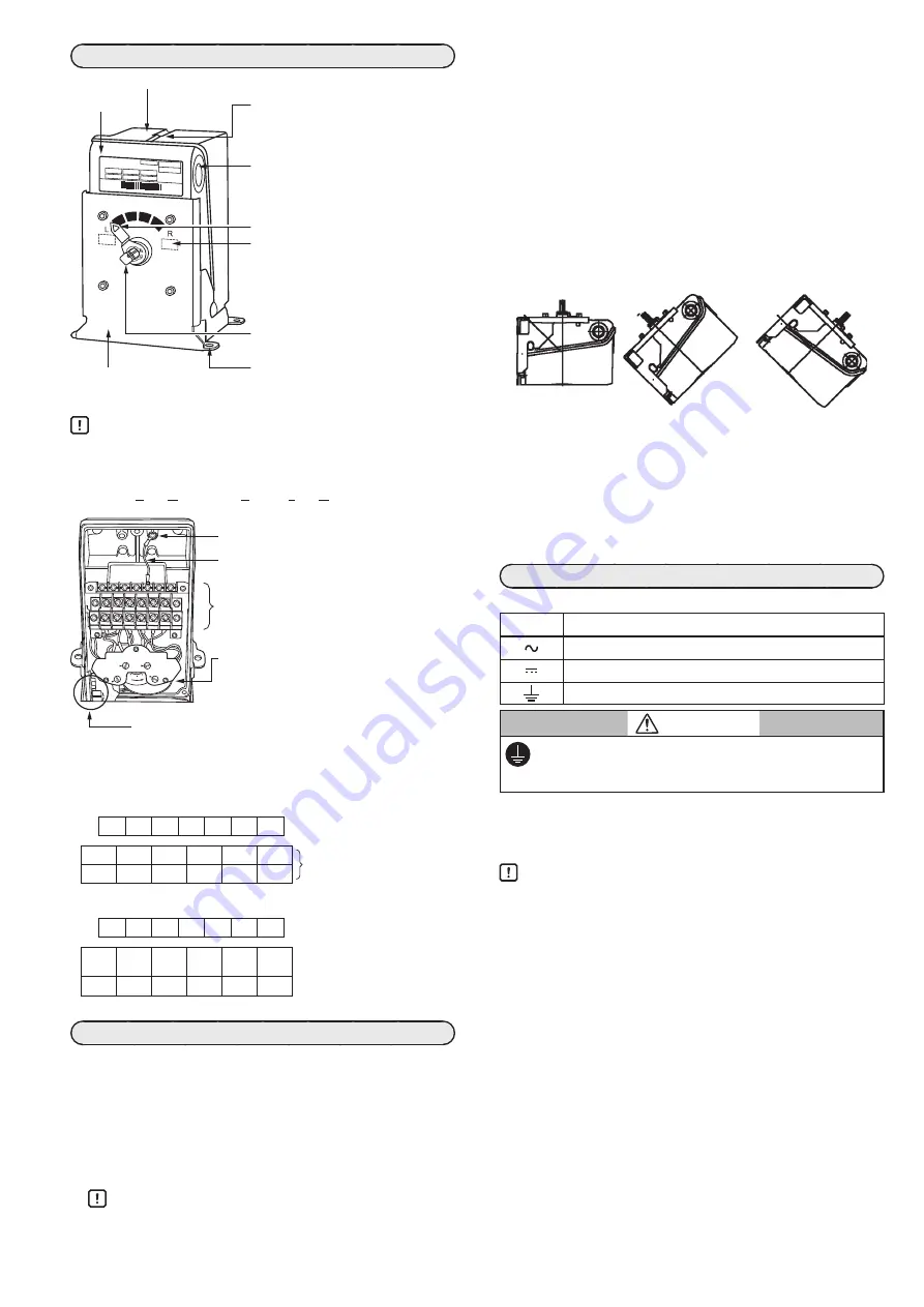
NAMES OF PARTS
Control Motor
ECM3000E9110
*123103800150*
Handling Precautions
• The default setting for the output shaft is 0 % opening.
• L: counterclockwise (CCW) rotation
R: clockwise (CW) rotation
CW: Clockwise CCW:
Counterclockwise
A
B
0
100
C
D
7
6
5
4
3 2
1
l
Terminal block
For 4 built-in auxiliary switches
7
6
5
4
3
2
1
For the power supply and signals
D3
D2
D1
C3
C2
C1
For auxiliary switches A to D
B3
B2
B1
A3
A2
A1
2 built-in auxiliary switches with forced open/close function
7
6
5
4
3
2
1
For the power supply and signals
S CONT CW CCW Not
used
Not
used
Forced open/close function
Auxiliary switches A and B
B3
B2
B1
A3
A2
A1
MOUNTING
Installation location
To install the ECM 3000, use the supplied bolt or equivalent (M6
size, with spring washer and flat washer). Use a nut (not supplied)
if necessary.
Bolt tightening torque: 4.1 to 5.2 N·m
Do not install the device in locations prohibited in the SAFETY
PRECAUTIONS section. For outdoor use, use a protective cover
or the like.
Handling Precautions
• Prevent foreign matter or moisture from entering the
device from the output shaft.
• When the motor is used with a control valve in an appli-
cation such as fluid control, if the control valve is located
higher than the motor, water drops may enter the motor
by running along the valve.
Mounting orientation
l
90° stroke model
This model can be mounted with any desired orientation.
However, take measures to prevent water and foreign matter
from entering the output shaft.
l
160° stroke model
This device can be mounted with the output shaft horizontal or
facing downwards. To prevent water drops from entering the
device, do not mount with the output shaft facing upward.
Incorrect
Incorrect
Incorrect
To ensure splash-proofing
Close the cover securely so that the packing and cable are not
pinched. Make the knockout hole watertight after wiring.
• Use a waterproof connector for the cables running from the
motor. Recommended waterproof connector: refer to the
sealing item of specifications
• If a conduit is used, use a waterproof precut tube or the like
to ensure waterproofing.
WIRING
Symbols used on the device:
Symbol
Meaning
AC power supply
DC signal
Functional ground terminal (not a protevtive ground terminal)
CAUTION
Make sure that the frame ground terminal is properly
grounded (100 Ω max.) using at least 2 mm
2
wire and
M4 crimp terminals with insulating sleeves.
During wiring, open a knockout hole (22 mm dia.) on either side,
and pull out the cables from the hole. For wiring to the terminals,
follow the terminal label indicated on the terminal block, and be sure
to use M3.5 crimp terminals with insulating sleeves.
Handling Precautions
• To open a knockout hole, using a flat-head screwdriver, set
its tip on the outer edge of the knockout plug, and lightly
tap the screwdriver all the way around this edge until the
knockout is removed.
• Do not allow any fragments to enter the actuator when the
knockout hole is opened.
• Do not use unused terminals on the device as relay
terminals.
• Be sure to attach the cover after wiring is complete.
• Do not run the signal wires in the same conduit as power lines.
• Keep power cables at least 50 cm away from signal cables.
• If the power and signal cables must run together in the
same conduit, use JCS4364-compliant instrument cable
for signals.
• Use the appropriate supply voltage according to the
model No.
• Be sure to install a circuit breaker (8A max) for the power
source.
• During motor operation, in order to stop hunting (which
causes the controller’s internal relay to turn ON and OFF
excessively), change the parameters of the controller.
For example, set the derivative time (D) to 0 seconds, set
a wider dead band, etc.
If the internal relay operates excessively, the life of the
motor or the host controller relay will be shortened.
Main unit
Resin cover: protects the inside of the device.
Cover retaining screw:
Secures the cover. 3 screws are used.
The recommended tightening torque
is 0.8 to 1.0 N·m.
Label [0],[100] (90° stroke models only):
When viewing the output shaft, “R”
indicates the valve opening direction
and “L” indicates the valve closing
direction.
Output shaft:
Moves the actuator via the linkage.
Pointer (90° stroke models only)
Mounting hole:
Located in the mounting bracket.
Bracket:
Used to mount the
control motor.
Knockout hole:
Used to run the wires out.
There is one hole each on the left
and right sides.
Frame ground terminal (use an M4 round
terminal lug for wiring)
Ground wire (E and G models only)
Terminal block:
Used for wiring. M3.5 screws are used.
Auxiliary switches (A, B, C, and D, or A and B):
Switches may be built into the motor de-
pending on the model.
Adjustment section of 4–20 mA DC input models:
Direct/reverse action can be switched, and zero/span
and dead band are adjustable.


