2
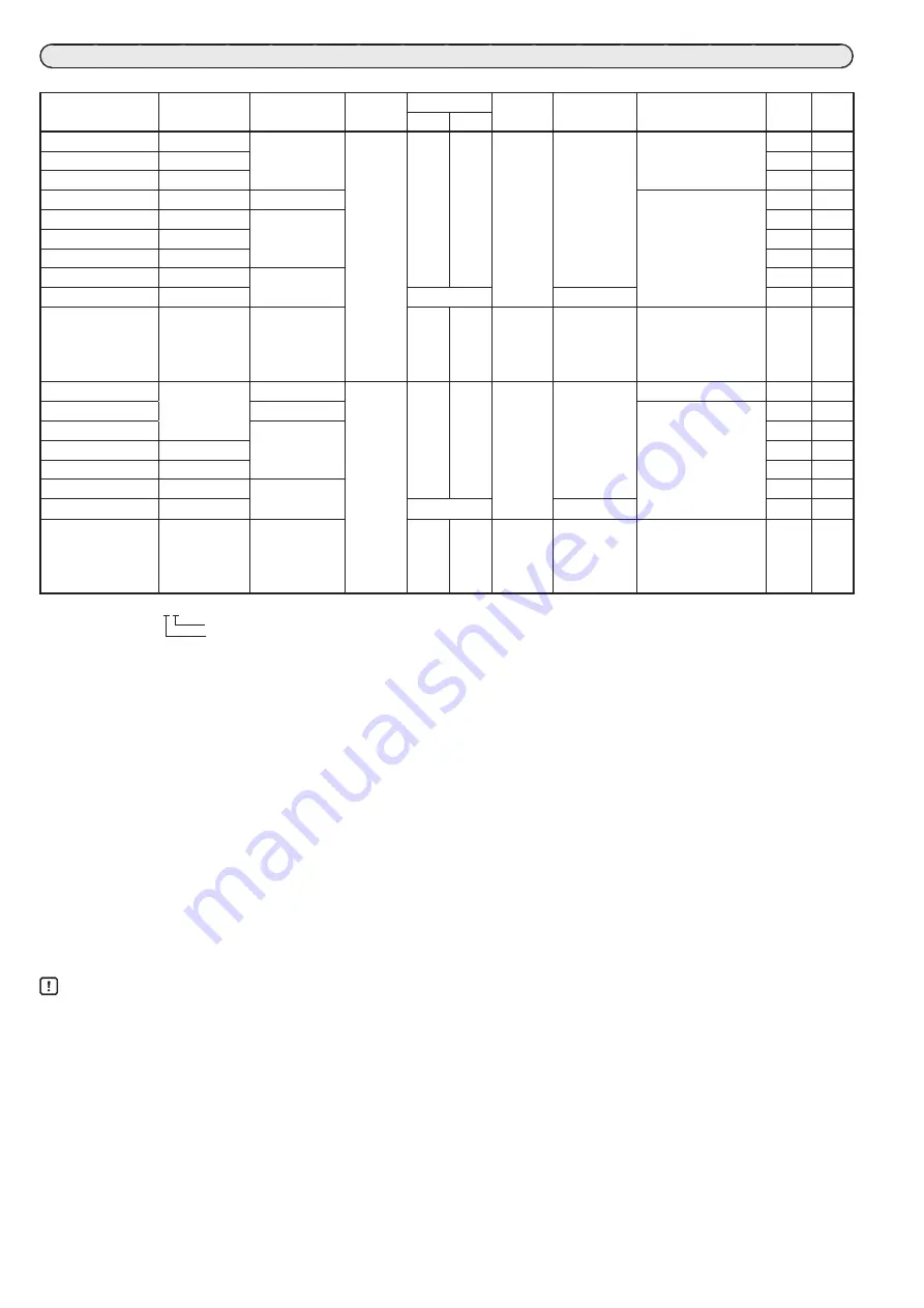
MODEL SELECTION TABLE
: Applicable —: Not applicable
Model No.
Power
Signal name
Rotation
angle
Rotation time
Output
torque
Power
consumption
Notes
UL*
1
*
8
CE*
1
*
9
50Hz
60Hz
ECM3000D01 _ _
24 V AC
Relay contacts
90°
39 s
33 s
12.5 N
・
m
9 VA*
4
ON/OFF operation
ECM3000D11 _ _
100 V AC
—
—
ECM3000D21 _ _
200 V AC
—
—
ECM3000E01 _ _
24 V AC
Potentiometer
Position proportional
operation
ECM3000F01 _ _
24 V AC
Relay contacts
ECM3000F11 _ _
100 V AC
—
—
ECM3000F21 _ _
200 V AC
—
—
ECM3000G01 _ _*
2
24 V AC
4
~
20 mA DC
ECM3000G91 _ _*
2
85
~
264 V AC
39 s
14 W*
5
—
—
ECM3000F03 _ _
24 V AC
Relay contacts
20 s
16 s
6 N
・
m
14 VA
High-speed motor
model
Position proportional
operation
—
ECM3000D020 _
24 V AC
Relay contacts
160°
69 s
58 s
12.5 N
・
m
9 VA*
4
ON/OFF operation
ECM3000E020 _
Potentiometer
Position proportional
operation
ECM3000F020 _
Relay contacts
ECM3000F120 _
100 V AC
—
—
ECM3000F220 _
200 V AC
—
—
ECM3000G02 _ _*
2
*
7
24 V AC
4
~
20 mA DC
ECM3000G92 _ _*
2
*
7
85
~
264 V AC
72 s
14 W*
5
—
—
ECM3000F040 _
24 V AC
Relay contacts
35 s
29 s
6 N
・
m
14 VA
High-speed motor
model
Position proportional
operation
—
(Example) ECM3000D01_ _
0 (zero): not GB-compliant, C: GB-compliant
0 (zero): No options*
3
3:
4 built-in auxiliary switches (for standard model. Contact current: 100 mA to 5 A [resistive load], 100 mA to 3 A [inductive
load])*
7
*
8
4:
2 built-in auxiliary switches (for standard model. Contact current: 100 mA to 5 A [resistive load], 100 mA to 3 A [in-
ductive load]) with forced open/close function*
6
*
8
5:
4 built-in auxiliary switches (for low-current model. Contact current: 1 to 100 mA [inductive load, including inrush
current])*
7
*
8
6:
2 built-in auxiliary switches (for low-current model. Contact current: 1 to 100 mA [inductive load, including inrush
current]) with forced open/close function*
6
*
8
*1. GB-compliant models are not compliant with UL or CE standards.
*2. Direct/reverse operation can be switched and zero point, span, and deadband can be adjusted. The device is adjusted at the factory with the direct opera-
tion setting. Readjustment is essential if the type of operation is switched.
*3. An extension unit can be mounted.
*4. Power consumption of the following models is 11 VA. ECM3000G014_, ECM3000G016_, ECM3000G024_, ECM3000G026_
*5. Power consumption of the following models is 15 W. ECM3000G914_, ECM3000G916_, ECM3000G924_, ECM3000G926_
*6. Selectable only for ECM3000G01_ _, ECM3000G91_ _, ECM3000G02_ _, ECM3000G92_ _.
*7. 4 built-in auxiliary switches models can not be selected.
*8. Use a class 2 power supplies with double or reinforced isolation from the MAINS power supply for the power supply and auxiliary switches.
*9. Use a limited-energy circuit (EN61010-1) with double or reinforced isolation from the MAINS power supply for the power supply and auxiliary switches.
Handling Precautions
• Use high-speed motor models at a duty ratio (operating ratio) of 40 % or less.
• Do not connect the ECM3000F to a mechanical balancing relay such as the R9107A or R927C. Doing so may apply excessive voltage to
the potentiometer, resulting in device failure.
• Be sure to connect non-voltage contacts to terminals S, CONT, CW, and CCW of an ECM3000 model with forced open/close function.
In the case of the M744 and M7284, 24 V AC may be applied to the S, CONT, CW, and CCW terminals.
If the ECM3000 is replaced with a forced open/close function model, do not apply 24 V AC to any terminal. Doing so will damage the
circuit.
• For the ECM3000F and ECM3000D, leakage current from the snubber circuit protecting the motor drive element (relay or SSR) must
be within the following.
• 100 V AC: 0.8 mA (RMS) max.
• 200 V AC: 0.4 mA (RMS) max.


