22
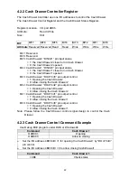
4.2.2 Cash Drawer Controller Register
The Cash Drawer Controller use one I/O addresses to control the Cash Drawer.
The Cash Drawer Control Register and the Cash Drawer Status Register.
Register Location: I/O port 4B8h
Attribute:
Read / Write
Size: 8bit
BIT
BIT7
BIT6
BIT5
BIT4
BIT3
BIT2
BIT1
BIT0
Attribute
Reserved
Reserved
Read
Read Write
Write
Write
Write
Bit 7: Reserved.
Bit 6: Reserved.
Bit 5: Cash Drawer2 “DIN bit1” pin input status.
= 1: the Cash Drawer2 closed or no Cash Drawer.
= 0: the Cash Drawer2 opened.
Bit 4: Cash Drawer1 “DIN bit0” pin input status.
= 1: the Cash Drawer1 closed or no Cash Drawer.
= 0: the Cash Drawer1 opened.
Bit 3: Cash Drawer2 “DOUT bit3” pin output control.
= 1: Opening the Cash Drawer2
= 0: Allow closing the Cash Drawer2
Bit 2: Cash Drawer2 “DOUT bit2” pin output control.
= 1: Opening the Cash Drawer2
= 0: Allow closing the Cash Drawer2
Bit 1: Cash Drawer1 “DOUT bit1” pin output control.
= 1: Opening the Cash Drawer1
= 0: Allow closing the Cash Drawer1
Bit 0: Cash Drawer1 “DOUT bit0” pin output control.
= 1: Opening the Cash Drawer1
= 0: Allow closing the Cash Drawer1
Note: Please follow the Cash Drawer control signal design to control the Cash
Drawer.
4.2.3 Cash Drawer Control Command Example
Use Debug.EXE program under DOS or Windows98
Command
Cash Drawer 1
O 4B8 01
Opening
O 4B8 00
Allow to closing
¾
Set the I/O address 4B8h bit0 =1 for opening the Cash Drawer1 by “DOUT bit0”
pin control.
¾
Set the I/O address 4B8h bit0 = 0 to allow closing Cash Drawer1.
Command
Cash Drawer 1
I 4B8
Check status
Содержание POS 460 Series
Страница 1: ...POS 460 Series Manual Point of Sale Hardware System PIN 48201123 2007 July V2 2 ...
Страница 19: ...c Click the YES button and restart your system 19 ...
Страница 37: ...g Pull the motherboard tray towards you to remove the motherboard 37 ...
Страница 40: ...Appendix B Jumper Settings B81 Motherboard JP6 JP3 JP15 JP14 JP13 JP12 JP10 JP11 JP9 JP5 JP4 JP2 JP1 40 ...


