General Instructions for 230V Machines
4
Good Working Practices/Safety
The following suggestions will enable you to observe
good working practices, keep yourself and fellow
workers safe and maintain your tools and equipment
in good working order.
WARNING!! KEEP TOOLS AND
EQUIPMENT OUT OF THE REACH
OF YOUNG CHILDREN
Keep the work area as uncluttered as is
practical, this includes personnel as well as
material. Under no circumstances should
CHILDREN be allowed in work areas.
Primary Precautions
These machines are supplied with a moulded 13
Amp. Plug and 3 core power cable. Before using the
machine inspect the cable and the plug to make
sure that neither are damaged. If any damage is
visible, have the tool inspected/repaired by a suitably
qualified person. If it is necessary to replace the plug,
it is preferable to use an ‘unbreakable’ type that will
resist damage. Only use a 13 Amp plug, and make
sure the cable clamp is tightened securely. Fuse as
required. If extension leads are to be used, carry out
the same safety checks on them, and ensure that they
are correctly rated to safely supply the current that is
required for your machine.
Work Place/Environment
Make sure when the machine is placed that it sits
firmly on the bench or stand, that it does not rock,
that it is sufficiently clear of adjacent obstacles so
that you have unimpeded access to all parts of the
machine. The machine is designed for indoor use, do
not use when or where it is liable to get wet. Keep
the machine clean; it will enable you to more easily
see any damage that may have occurred. Clean the
overall machine with a damp soapy cloth if needs
be, do not use any solvents or cleaners, as these may
cause damage to any plastic parts or to the electrical
components. Clean the machine components with
a lightly oiled cloth. If the machine is liable to be
standing idle for any length of time a light coat of
machine or spray oil will minimise rusting.
It is good practice to leave the machine unplugged
until work is about to commence, also make sure
to unplug the machine when it is not in use, or
unattended. Always disconnect by pulling on the
plug body and not the cable. Once you are ready to
commence work, remove all tools used in the
setting operations and place safely out of the way.
Re-connect the machine.
Carry out a final “tightness” check e.g. chuck or face
plate, workpiece, tool rest, etc., check that the
correct speed has been selected.
Make sure you are comfortable before you start
work, balanced, not reaching etc. If the work you are
carrying out is liable to generate flying grit, dust or
chips, wear the appropriate safety clothing, goggles,
gloves, masks etc. If the work operation appears
to be excessively noisy, wear ear-defenders. If you
wear your hair in a long style, wearing a cap, safety
helmet, hairnet, even a sweatband, will minimise
the possibility of your hair being caught up in the
rotating parts of the tool, likewise, consideration
should be given to the removal of rings and
wristwatches, if these are liable to be a ‘snag’ hazard.
Consideration should also be given to non-slip
footwear, etc.
DO NOT work with cutting tools of any description if
you are tired, your attention is wandering or you
are being subjected to distraction. A deep cut, a
lost fingertip or worse; is not worth it! Above all,
OBSERVE…. make sure you know what is happening
around you, and USE YOUR COMMON SENSE.
Содержание AT1628VS
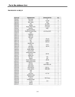
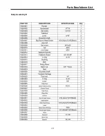
Страница 15: ...Parts Breakdown List 15 Headstock Assembly A...
Страница 16: ...Parts Breakdown List 16 Headstock Assembly A...
Страница 17: ...Parts Breakdown List 17 Headstock Assembly A...
Страница 18: ...Parts Breakdown List 18 Body Assembly B...
Страница 19: ...Parts Breakdown List 19 Body Assembly B...
Страница 20: ...Parts Breakdown List 20 Stand Assembly C Optional...
Страница 21: ...Parts Breakdown List 21...
Страница 22: ...Wiring Diagram 22...
Страница 23: ...Notes 23...


