IPC960/IPC962/IPC964-525 Series U
ser’s Manual
Hardware Installation
59
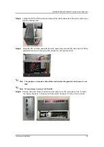
Step 9
Fasten the holder bracket in the chassis, a djust the screw position of the
extension bracket to fix the add-on card, and then screw it.
Step 10
Close the cover back to the chassis and fasten the screw. The installation
is complete.
2.7.2 The height limitation of an add-on card
Please note that the extension holder bracket suppor ts the height of an add-on card
from 49.48mm to 119.78mm.
IPC962
IPC964
Содержание IPC960-525 Series
Страница 1: ...IPC960 525 series IPC962 525 series IPC964 525 series Industrial Computers User s Manual...
Страница 17: ...IPC960 IPC962 IPC964 525 Series User s Manual Introduction 9 IPC964 525...
Страница 52: ...IPC960 IPC962 IPC964 525 Series User s Manual Introduction 44 This page is intentionally left blank...
Страница 86: ...IPC960 IPC962 IPC964 525 Series User s Manual Hardware Installation 78 This page is intentionally left blank...
Страница 94: ...IPC960 IPC962 IPC964 525 Series User s Manual AMI BIOS Utility 86 ME Display ME firmware information...
Страница 99: ...IPC960 IPC962 IPC964 525 Series User s Manual AMI BIOS Utility 91 AMT Configuration...
Страница 103: ...IPC960 IPC962 IPC964 525 Series User s Manual AMI BIOS Utility 95 Compatibility Support Module CSM Configuration...
Страница 104: ...IPC960 IPC962 IPC964 525 Series User s Manual AMI BIOS Utility 96 PCI Subsystem Setting...
Страница 107: ...IPC960 IPC962 IPC964 525 Series User s Manual AMI BIOS Utility 99 PEG Port Configuration PEG Port Feature Configuration...
Страница 109: ...IPC960 IPC962 IPC964 525 Series User s Manual AMI BIOS Utility 101 Memory Configuration...
Страница 114: ...IPC960 IPC962 IPC964 525 Series User s Manual AMI BIOS Utility 106 This page is intentionally left blank...


