background image

IPC960/IPC962/IPC964-525  Series U

ser’s Manual 


Hardware Installation 

51 


Step 4  

Loosen the screw to remove the system cover from the expansion box kit. 


Содержание IPC960-525 Series

Страница 1: ...IPC960 525 series IPC962 525 series IPC964 525 series Industrial Computers User s Manual...

Страница 2: ...efulness of any information in this document Axiomtek does not make any commitment to update the information in this manual Axiomtek reserves the right to change or revise this document and or product...

Страница 3: ...64 525 Series is properly grounded 4 Make sure the voltage of the power source is correct before connecting the equipment to the power outlet 5 Turn OFF the system power before cleaning Clean the syst...

Страница 4: ...clean any single part or component for the computer please read and understand the details below fully When you need to clean the device please rub it with a piece of dry cloth 1 Be cautious of the ti...

Страница 5: ...some water or rubbing alcohol and rub it on the computer Unknown solvents may be harmful to the plastics parts Vacuum cleaner Vacuuming the dust dirt hair cigarette particles and other particles out...

Страница 6: ...ng in case computers are out of order or no longer in use Trademark Acknowledgments Axiomtek is a trademark of Axiomtek Co Ltd Intel and Pentium are registered trademarks of Intel Corporation Windows...

Страница 7: ...25 1 8 10 M 2 3050 Key B CN5 26 1 8 11 SATA Power Connector SCN2 27 1 8 12 SATA Connector SATA1 SATA2 27 1 8 13 Power On OFF Button SW2 27 1 8 14 AT ATX Switch SSW1 28 1 8 15 Remote Power Switch Conne...

Страница 8: ...ling T4 graphics card w T4 fan module 62 2 8 Installing the Mini Card Module 68 2 9 Installing the 5G Wireless Module 69 2 10 Installing the NVMe SSD Module 72 2 11 Mounting 74 SECTION 3 AMI BIOS UTIL...

Страница 9: ...62 525 and IPC964 525 are fanless systems with an optional fan module that can support LGA1151 socket for Intel 9th 8th generation Core TM i7 i5 i3 processors The IPC960 525 IPC962 525 IPC964 525 is a...

Страница 10: ...sh i3 9320 62 4 4 3 7 GHz Coffee Lake S refresh i3 9300 62 4 4 3 7 GHz Coffee Lake S refresh G4950 54 2 2 3 3 GHz Coffee Lake S refresh G4930 54 2 2 3 2 GHz Coffee Lake S refresh i7 9700TE 35 8 8 1 8...

Страница 11: ...t View and Customer CMOS Backup System Memory Two DDR4 2666 2400 un buffered SO DIMM max up to 64GB System Certification CE FCC Features Compact front IO design Supports PCIe PCI expansion slots DC to...

Страница 12: ...gnal for H310 PCH Note The RS 485 auto flow control only supports below formats to communicate data 8 data bits 1 stop bit 8 data bits 1 parity bit 1 stop bit 8 data bits 1 parity bit 2 stop bits 8 da...

Страница 13: ...o use Gen 3 SSD on the IPC962 Series Power Input 24VDC uMin 19V uMax 30V with phoenix power plug Note Please fix the system power input in 24Vdc when plugging an add on card Operating Temperature Gene...

Страница 14: ...refresh i3 9100TE 35 4 4 10 60 2 2 GHz Coffee Lake S refresh i3 9100T 35 4 4 10 60 3 1 GHz Coffee Lake S refresh G4930T 35 2 2 10 60 3 0 GHz Coffee Lake S i7 8700 65 6 12 10 50 3 2 GHz Coffee Lake S...

Страница 15: ...the system might be adversely affected when operating at a temperature above the system s limitation or with an unrecommended processor Note If the operating temperature is above 35 C it is recommende...

Страница 16: ...IPC960 IPC962 IPC964 525 Series User s Manual Introduction 8 1 3 Dimensions The following diagrams show you dimensions and outlines of the IPC960 525 IPC962 525 IPC964 525 Series IPC960 525 IPC962 525...

Страница 17: ...IPC960 IPC962 IPC964 525 Series User s Manual Introduction 9 IPC964 525...

Страница 18: ...oduction 10 1 4 I O Outlets The following figures show locations of the IPC900 series I O outlets IPC960 525 Front Panel Mark Description 1 1 x HDD SSD access LED 3 x User s LED 2 1 x 4 pin terminal b...

Страница 19: ...r s Manual Introduction 11 5 1 x VGA 6 1 x HDMI 7 1 x Switch for power on off w LED 8 Extension system I O module 9 1 x Line out 10 1 x Remote switch 11 2 x USB2 0 12 4 x USB 3 1 13 1 x AT ATX switch...

Страница 20: ...64 525 Series User s Manual Introduction 12 IPC962 525 Front Panel Mark Description 1 1 x HDD SSD access LED 3 x User s LED 2 1 x 4 pin terminal block 3 1 x RS 232 422 485 default RS 232 4 2 x LAN 5 1...

Страница 21: ...nual Introduction 13 7 Riser PCIe PCI slots expansion 8 1 x Switch for power on off w LED 9 Extension system I O module 10 1 x Line out 11 1 x Remote switch 12 2 x USB2 0 13 4 x USB 3 1 14 1 x AT ATX...

Страница 22: ...2 IPC964 525 Series User s Manual Introduction 14 IPC964 525 Front Panel Mark Description 1 1 x HDD SSD access LED 3 x User s LED 2 1 x 4 pin terminal block 3 1 x RS 232 422 485 default RS 232 4 2 x L...

Страница 23: ...ntroduction 15 6 1 x HDMI 7 Riser PCIe PCI slots expansion 8 1 x Switch for power on off w LED 9 Extension system I O module 10 1 x Line out 11 1 x Remote switch 12 2 x USB2 0 13 4 x USB 3 1 14 1 x AT...

Страница 24: ...ould contain the following items IPC960 525 IPC962 525 IPC964 525 Series unit x 1 Screw pack x 1 Foot pad x 4 CPU grease x 1 Terminal block x 1 Remote switch cable x 1 Holder bracket kit x1 for IPC962...

Страница 25: ...IPC960 IPC962 IPC964 525 Series User s Manual Introduction 17 1 6 M B Block Diagram The following diagram shows you the M B block diagram of SBC87525...

Страница 26: ...n the jumper Open Closed Pin1 2 Closed Jumper Descriptions Setting JP2 Clear RTC Normal Short 1 2 JP10 JP11 DELAY Function SW Short 1 2 1 7 1 Restore BIOS Optimal Defaults JP2 Put jumper clip to pin 2...

Страница 27: ...onnector CN2 M 2 2280 Key M NVMe SSD CN8 M 2 3050 Key B CN5 COM port connector COM1 SATA Power connector SCN2 SATA III connector SATA1 2 DDR4 SO DIMM 260 Pin SDIMM1 SDIMM2 Power button SW2 AT ATX Powe...

Страница 28: ...No use 18 GND 19 No use 20 W_DISABLE 21 GND 22 PERST 23 PE_RXN3 SATA_RXP 24 3 3VSB 25 PE_RXP3 SATA_RXN 26 GND 27 GND 28 1 5V 29 GND 30 SMB_CLK 31 PE_TXN3 SATA_TXN 32 SMB_DATA 33 PE_TXP3 SATA_TXP 34 G...

Страница 29: ..._VCC 5V level standby power 10 USB_VCC 5V level standby power 2 USB_Data2 11 USB_Data3 3 USB_Data2 12 USB_Data3 4 GND 13 GND 5 SSRX2 14 SSRX3 6 SSRX2 15 SSRX3 7 GND 16 GND 8 SSTX2 17 SSTX3 9 SSTX2 18...

Страница 30: ...3 VGA Connector CN3 The CN9 is a 15 pin D Sub connector which is commonly used for connecting a CRT monitor Pins Signals Pins Signals 1 Red 2 Green 3 Blue 4 N C 5 GND 6 DETECT 7 GND 8 GND 9 5V 10 GND...

Страница 31: ...r etc 1 8 5 Audio Connector CN1 These two audio jacks are ideal for Audio Mic In and Audio Line out Pins Signals 1 Line Out 1 8 6 DC in Phoenix Power Connector CN12 The system supports the 24VDC uMin...

Страница 32: ...T_SCL 6 HDMI OUT_DATA1 16 HDMI OUT_SDA 7 HDMI OUT_DATA0 17 GND 8 GND 18 5V 9 HDMI OUT_DATA0 19 HDMI_HTPLG 10 HDMI OUT Clock 1 8 8 COM Port Connector COM1 The system has a serial port COM1 is RS 232 42...

Страница 33: ...V 19 PERp2 20 NC 21 GND 22 NC 23 PETn2 24 NC 25 PETp2 26 NC 27 GND 28 NC 29 PERn1 30 NC 31 PERp1 32 NC 33 GND 34 NC 35 PETn1 36 NC 37 PETp1 38 NC 39 GND 40 NC 41 PERn0 42 NC 43 PERp0 44 NC 45 GND 46 N...

Страница 34: ..._6 23 GPIO_11 24 GPIO_7 25 DPR 26 GPIO_10 27 GND 28 GPIO_8 29 USB3 1 Tx 30 UIM RESET 31 USB3 1 Tx 32 UIM CLK O 33 GND 34 UIM DATA I O 35 USB3 1 Rx 36 UIM PWR O 37 USB3 1 Rx 38 NC 39 GND 40 GPIO_0 41 P...

Страница 35: ...hnology Attachment Serial ATA or SATA connectors are used as high speed SATA interfaces They are computer bus interfaces for connecting to devices such as hard disk drives This board has two SATA 3 0...

Страница 36: ...tion Description Short 1 2 Turn on off system Open Keep system status 1 8 16 Flexible IO COM I O Card Connector AX93511 The system has an optional four serial port module COM2 COM5 are RS 232 422 485...

Страница 37: ...se refer to Chapter 4 for the details of BIOS setting COM2 COM3 COM4 COM5 Pins RS 232 RS 422 RS 485 1 DCD Data Carrier Detect TX Data 2 RXD Receive Data TX Data 3 TXD Transmit Data RX No use 4 DTR Dat...

Страница 38: ...CD Data Carrier Detect TX Data 2 RXD Receive Data TX Data 3 TXD Transmit Data RX No use 4 DTR Data Terminal Ready RX No use 5 GND Ground No use No use 6 DSR Data Set Ready No use No use 7 RTS Request...

Страница 39: ...f the isolated digital input channels accepts 0 30 VDC with sink type and source type Isolated Digital Output The figure shows how to connect between an output channel and the system If an external vo...

Страница 40: ...IOS setting AX93519 2 x RS232 422 485 1 G E LAN i211AT 2 USB 3 1 1 USB3 1 Gen 2 signal 1 USB 2 0 signal for Q370 PCH AX93519 2 x RS232 422 485 1 G E LAN i211AT 2 USB 3 1 2 USB 2 0 signal for H310 PCH...

Страница 41: ...ansmit Data RX No use 4 DTR Data Terminal Ready RX No use 5 GND Ground No use No use 6 DSR Data Set Ready No use No use 7 RTS Request To Send No use No use 8 CTS Clear To Send No use No use 9 RI Ring...

Страница 42: ...ek s device only Note Please refer to chapter 1 2 2 for the maximum power rating limitation of expansion slots Internal USB Wafer connector CN1 These are 5x1 Pin P 2 0mm headers for USB 2 0 interface...

Страница 43: ...s Signals 1 GND 2 GND 3 12V 4 12V ATX1 is reserved for Axiomtek s device use only Temperature Sensor Source Select JP1 Use these jumpers 3x1 Pin P 2 54mm to set temperature sensor source to operate fr...

Страница 44: ...vice only Note Please refer to chapter 1 2 2 for the maximum power rating limitation of expansion slots Internal USB Wafer connector CN1 These are 5x1 Pin P 2 0mm headers for USB 2 0 interface Pins Si...

Страница 45: ...s Signals 1 GND 2 GND 3 12V 4 12V ATX1 is reserved for Axiomtek s device use only Temperature Sensor Source Select JP1 Use these jumpers 3x1 Pin P 2 54mm to set temperature sensor source to operate fr...

Страница 46: ...ease refer to chapter 1 2 2 for the maximum power rating limitation of expansion slots Internal USB Wafer connector CN1 These are 5x1 Pin P 2 0mm headers for USB 2 0 interface Pins Signals 1 5V_DUAL 2...

Страница 47: ...Signals 1 GND 2 GND 3 12V 4 12V ATX1 is reserved for Axiomtek s device use only Temperature Sensor Source Select JP1 Use these jumpers 3x1 Pin P 2 54mm to set temperature sensor source to operate from...

Страница 48: ...k s device only Note Please refer to chapter 1 2 2 for the maximum power rating limitation of expansion slots Internal USB Wafer connector CN1 These are 5x1 Pin P 2 0mm headers for USB 2 0 interface P...

Страница 49: ...Signals 1 GND 2 GND 3 12V 4 12V ATX1 is reserved for Axiomtek s device use only Temperature Sensor Source Select JP1 Use these jumpers 3x1 Pin P 2 54mm to set temperature sensor source to operate from...

Страница 50: ...xiomtek s device only Note Please refer to chapter 1 2 2 for the maximum power rating limitation of expansion slots Internal USB Wafer connector CN1 These are 5x1 Pin P 2 0mm headers for USB 2 0 inter...

Страница 51: ...s Signals 1 GND 2 GND 3 12V 4 12V ATX1 is reserved for Axiomtek s device use only Temperature Sensor Source Select JP1 Use these jumpers 3x1 Pin P 2 54mm to set temperature sensor source to operate fr...

Страница 52: ...IPC960 IPC962 IPC964 525 Series User s Manual Introduction 44 This page is intentionally left blank...

Страница 53: ...rtant Notes Before attempting to install a new processor carefully review the documentation that came with your system and make sure that you will not be voiding your warranty by opening the computer...

Страница 54: ...ect the power connector Step 3 Loosen four screws to remove the heatsink cover from the chassis Step 4 After opening the heatsink cover you can locate the CPU socket as marked Align pins of the CPU wi...

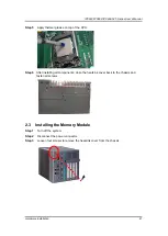
Страница 55: ...se on top of the CPU Step 6 After installing all components close the heatsink cover back to the chassis and fasten all screws 2 3 Installing the Memory Module Step 1 Turn off the system Step 2 Discon...

Страница 56: ...the memory modules close the heatsink cover back to the chassis and fasten all screws 2 4 Installing the Hard Disk Drive The IPC960 525 IPC962 525 IPC964 525 Series offers a convenient drive bay modu...

Страница 57: ...ation 49 Step 5 Align the connector of the HDD SSD with the SATA slot of main board Then insert the HDD into the HDD tray Note When using 7mm height HDD SDD please take the HDD spacer out of the acces...

Страница 58: ...ray 2in1 is as shown below 2 5 Installing the expansion box kit The IPC960 525 FL provides two four slot expansion box kit for expansion purposes The procedure of installing the expansion box kit into...

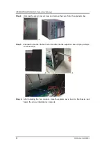
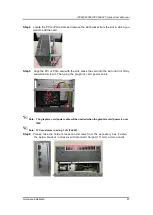
Страница 59: ...IPC960 IPC962 IPC964 525 Series User s Manual Hardware Installation 51 Step 4 Loosen the screw to remove the system cover from the expansion box kit...

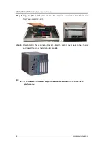
Страница 60: ...the slot and press the card into the slot until it is firmly seated and screw it Step 6 After installing the expansion box kit close the system cover back to the chassis and fasten the screw Installat...

Страница 61: ...n module or an external fan module for optional selection The procedure of installing the fan module into system is instructed below 2 6 1 Installing Internal Fan Module Step 1 Please take the Mylar o...

Страница 62: ...stem cover screw and remove the cover from the expansion box Step 5 Unscrew the bracket fasten the fan module into the expansion box and plug cable s to connector s Step 6 After installing the fan mod...

Страница 63: ...ng external Fan Module Step 1 Please take the Mylar out of the accessory box Screw the fan to the fan bracket IPC962 series IPC964 series Step 2 Turn off the system Step 3 Disconnect the power connect...

Страница 64: ...n is complete Note Reserve at least 25mm space from the rear side for optimal fan air flow 2 7 Installing PCI or PCIe Card The IPC962 525 FL IPC964 525 FL provides two four PCI or PCIe slots for expan...

Страница 65: ...PCIe card with the slot press the card into the slot until it is firmly seated and screw it Then plug the graphics card power cable Note The graphics card power cable will be needed when the graphics...

Страница 66: ...tep 7 IPC962 and IPC964 offer 3 types of extension holder brackets Please take the brackets and screws from the accessory box and assemble the extension holder bracket The procedure is illustrated bel...

Страница 67: ...osition of the extension bracket to fix the add on card and then screw it Step 10 Close the cover back to the chassis and fasten the screw The installation is complete 2 7 2 The height limitation of a...

Страница 68: ...w o add on card power cable w o internal fan module Note Please note that 234mm is the maximum length for add on card with I O bracket Considering heat dissipation potential a space of 30mm must be l...

Страница 69: ...left between add on card and option fan Note Please note that 210mm is the maximum internal length for add on card with I O bracket Considering heat dissipation potential a space of 20mm must be left...

Страница 70: ...er s Manual Hardware Installation 62 2 7 4 Inatalling T4 graphics card w T4 fan module Step 1 Please take the Mylar from the accessory box Then paste it on the cover s vents Step 2 Please take the fan...

Страница 71: ...64 525 Series User s Manual Hardware Installation 63 Step 3 Screw the eight screws into fan and fan bracket Step 4 Paste the 4 poron pads on air duct brackets as illustrated below Step 5 Screw the bra...

Страница 72: ...ies User s Manual Hardware Installation 64 Step 6 Screw the fan module into chassis and plug in the fan connectors Step 7 Route the cables and put the cables in red mark area as illustrated below Step...

Страница 73: ...t s metal part as marked A below and screw the 4 screws Step 10 Align the T4 card with the slot press the card into the slot until it is firml y seated and screw the T4 card bracket and slot bracket t...

Страница 74: ...Step 13 Close the cover back to the chassis and fasten the screw The installation is complete Note Please note the T4 FAN module kit supports IPC962 w AX96205 and IPC960 w AX96205 expansion box kit on...

Страница 75: ...IPC962 System configuration w AX96205 T4 w T4 fan module kit Note Please note that 165mm of the 2 nd slot is the maximum length for add on card with I O bracket considering heat dissipation potential...

Страница 76: ...refer to the following instructions and illustrations for the installation of the wireless LAN Step 1 Please take the wireless LAN card from the accessory box Step 2 Turn off the system Step 3 Discon...

Страница 77: ...B PCIe interface IPC962 525 Q370 IPC964 525 Q370 b 1 x on board full size PCI Express Mini Card slot with USB interface IPC962 525 H310 Note The IPC960 IPC962 and IPC964 support either a mini card slo...

Страница 78: ...ep 4 Disconnect the power connector Step 5 Loosen screws to remove the heatsink cover from the chassis Step 6 Insert the 5G wireless module into the slot and push it down firmly Then screw the card ti...

Страница 79: ...on the antenna connectors as marked in the illustration below and then insert the SIM card into the SIM slot Step 9 Close the cover back to the chassis and fasten all screws The installation is compl...

Страница 80: ...ase refer to the following instructions and illustrations for the installation of the NVMe SSD module Step 1 Please take the NVMe SSD module kit from the accessory box Step 2 Turn off the system Step...

Страница 81: ...down firmly Then screw the card tightly to the mainboard Step 7 Paste the other thermal pad on the module and then remove the protective film as illustrated below Step 8 Close the cover back to the c...

Страница 82: ...on 74 2 11 Mounting The IPC960 525 IPC962 525 IPC964 525 provides versatile mount kits for optional selection DIN rail mounting Note The DIN rail kit can be installed in IPC960 system only Wall mounti...

Страница 83: ...IPC960 IPC962 IPC964 525 Series User s Manual Hardware Installation 75 IPC960 525 System w din rail kit System w wall mount kit...

Страница 84: ...IPC960 IPC962 IPC964 525 Series User s Manual Hardware Installation 76 IPC962 525 System w wall mount kit System w external fan module and wall mount kit...

Страница 85: ...IPC960 IPC962 IPC964 525 Series User s Manual Hardware Installation 77 IPC964 525 System w wall mount kit System w external fan module and wall mount kit...

Страница 86: ...IPC960 IPC962 IPC964 525 Series User s Manual Hardware Installation 78 This page is intentionally left blank...

Страница 87: ...1 Starting To enter the setup screens follow the steps below 1 Turn on the computer and press the Del key immediately 2 After you press the Del key the main BIOS setup menu displays You can access th...

Страница 88: ...ub screen Plus Minus The Plus and Minus Arrow keys allow you to change the field value of a particular setup item Tab The Tab key allows you to select setup fields F1 The F1 key allows you to display...

Страница 89: ...ting the Main tab System Time Date can be set up as described below The Main BIOS setup screen is shown below System Date Time Use this option to change the system time and date Highlight System Time...

Страница 90: ...le or disable the boot ROM function of the onboard LAN chip when the system boots up The Advanced menu also allows users to set configuration of the CPU and other system devices You can select any of...

Страница 91: ...IPC960 IPC962 IPC964 525 Series User s Manual AMI BIOS Utility 83 HW Monitor This screen monitors hardware health...

Страница 92: ...IPC960 IPC962 IPC964 525 Series User s Manual AMI BIOS Utility 84 7802Y HW Monitor This screen monitors fan speed...

Страница 93: ...IPC960 IPC962 IPC964 525 Series User s Manual AMI BIOS Utility 85 Ethercat Configuration Setting Disable mode in the following 5 times to support Ethercat...

Страница 94: ...IPC960 IPC962 IPC964 525 Series User s Manual AMI BIOS Utility 86 ME Display ME firmware information...

Страница 95: ...figuration can be configured in ACPI Settings A description of the selected item appears on the right side of the screen ACPI Sleep State Select the highest ACPI sleep state the system will enter when...

Страница 96: ...IPC960 IPC962 IPC964 525 Series User s Manual AMI BIOS Utility 88 Trusted Computing Select Security Device Support to enable or disable the TPM function...

Страница 97: ...his screen shows the CPU configuration and you can change the value of the selected option Intel Virtualization Technology This item allows a hardware platform to run multiple operating systems separa...

Страница 98: ...AMI BIOS Utility 90 SATA and RST Configuration You can read the current installed hardware configurations from those SATA ports in the SATA and RST Configuration menu During system boot up BIOS will...

Страница 99: ...IPC960 IPC962 IPC964 525 Series User s Manual AMI BIOS Utility 91 AMT Configuration...

Страница 100: ...anual AMI BIOS Utility 92 USB Configuration USB configuration can be configured here by selecting and changing each item A description of the selected item appears on the right side of the screen USB...

Страница 101: ...IPC960 IPC962 IPC964 525 Series User s Manual AMI BIOS Utility 93 F81803 Super IO Configuration Serial Port 1 4 Configuration Use this item to set parameters of serial port 1 to 4...

Страница 102: ...IPC960 IPC962 IPC964 525 Series User s Manual AMI BIOS Utility 94 Serial Port 1 4 Console COM Port Type Use this item to set parameters of RS232 422 485...

Страница 103: ...IPC960 IPC962 IPC964 525 Series User s Manual AMI BIOS Utility 95 Compatibility Support Module CSM Configuration...

Страница 104: ...IPC960 IPC962 IPC964 525 Series User s Manual AMI BIOS Utility 96 PCI Subsystem Setting...

Страница 105: ...525 Series User s Manual AMI BIOS Utility 97 3 5 Chipset Menu The Chipset menu allows users to change the advanced chipset settings You can select any of the items in the left frame of the screen to...

Страница 106: ...IPC960 IPC962 IPC964 525 Series User s Manual AMI BIOS Utility 98 System Agent SA Configuration For items marked with please press Enter for more options...

Страница 107: ...IPC960 IPC962 IPC964 525 Series User s Manual AMI BIOS Utility 99 PEG Port Configuration PEG Port Feature Configuration...

Страница 108: ...IPC960 IPC962 IPC964 525 Series User s Manual AMI BIOS Utility 100 Graphics Configuration Display Select Allows you to select which graphics controller to use as the primary boot device...

Страница 109: ...IPC960 IPC962 IPC964 525 Series User s Manual AMI BIOS Utility 101 Memory Configuration...

Страница 110: ...e Security menu allows users to change the security settings for the system Administrator Password This item indicates whether an administrator password has been set installed or uninstalled User Pass...

Страница 111: ...ite waiting Bootup NumLock State Use this item to select the power on state for the keyboard NumLock Quiet Boot Select to display either POST output messages or a splash screen during boot up Launch P...

Страница 112: ...Select Yes to save changes and exit Discard Changes and Exit Select this option to quit Setup without making any permanent changes to the system configuration and return to Main Menu Select Discard C...

Страница 113: ...g any permanent changes to the system configuration Select Discard Changes from the Save Exit menu and press Enter Select Yes to discard changes Restore Defaults After selecting this option all the se...

Страница 114: ...IPC960 IPC962 IPC964 525 Series User s Manual AMI BIOS Utility 106 This page is intentionally left blank...

Страница 115: ...gers a system reset when it counts down to zero from a preset value The software starts the counter with an initial value and must reset it periodically If the counter ever reaches zero which means th...

Страница 116: ...ries User s Manual Watchdog Timer 108 Begin Enable and Initialize Watchdog Timer Program A Disable Watchdog Timer Next Next Next Next Begin Enable and Initialize Watchdog Timer Program A Reset Watchdo...

Страница 117: ...al 87 Un lock super I O out dx al out dx al Select Logic device mov dx 2Eh mov al 07h out dx al mov dx 2Fh mov al 07h out dx al Enable WDT base address mov dx 2Eh mov al 30h out dx al mov dx 2Fh mov a...

Страница 118: ...below out dx al Note If N 71h the time base is set to second M time value 00 Time out disable 01 Time out occurs after 1 second 02 Time out occurs after 2 seconds 03 Time out occurs after 3 seconds FF...

Страница 119: ...ler mode and boot sequence 3 Configure RAID using the RAID BIOS 1 Installing SATA hard drive s in your system Connect one end of the SATA signal cable to the rear of the SATA hard drive and the other...

Страница 120: ...figure a RAID array Skip this step and proceed if you do not want to create a RAID 3 1 After the POST memory testing and before the operating system booting a message Press Ctrl I to enter Configurati...

Страница 121: ...reate Volume Menu screen you can type the disk array name with 1 16 letters letters cannot be special characters in the item Name 3 4 When finished press Enter to select a RAID level There are two RAI...

Страница 122: ...t the stripe block size The KB is the standard unit of stripe block size The stripe block size can be 4KB to 128KB After the setting press Enter for the array capacity 3 6 After setting all the items...

Страница 123: ...When prompting for confirmation press Y to create this volume or N to cancel the creation After the creation is complete you will see detailed information about the RAID array in the Disk Volume Info...

Страница 124: ...elete RAID volume If you want to delete a RAID volume select the Delete RAID Volume option in Main Menu Press Enter and follow on screen instructions Please press Esc to exit the RAID BIOS utility Now...

Отзывы: