background image

eBOX640-521-FL Series U

ser’s Manual 


BIOS Setup Utility 


51 

4.8 

Save & Exit Menu


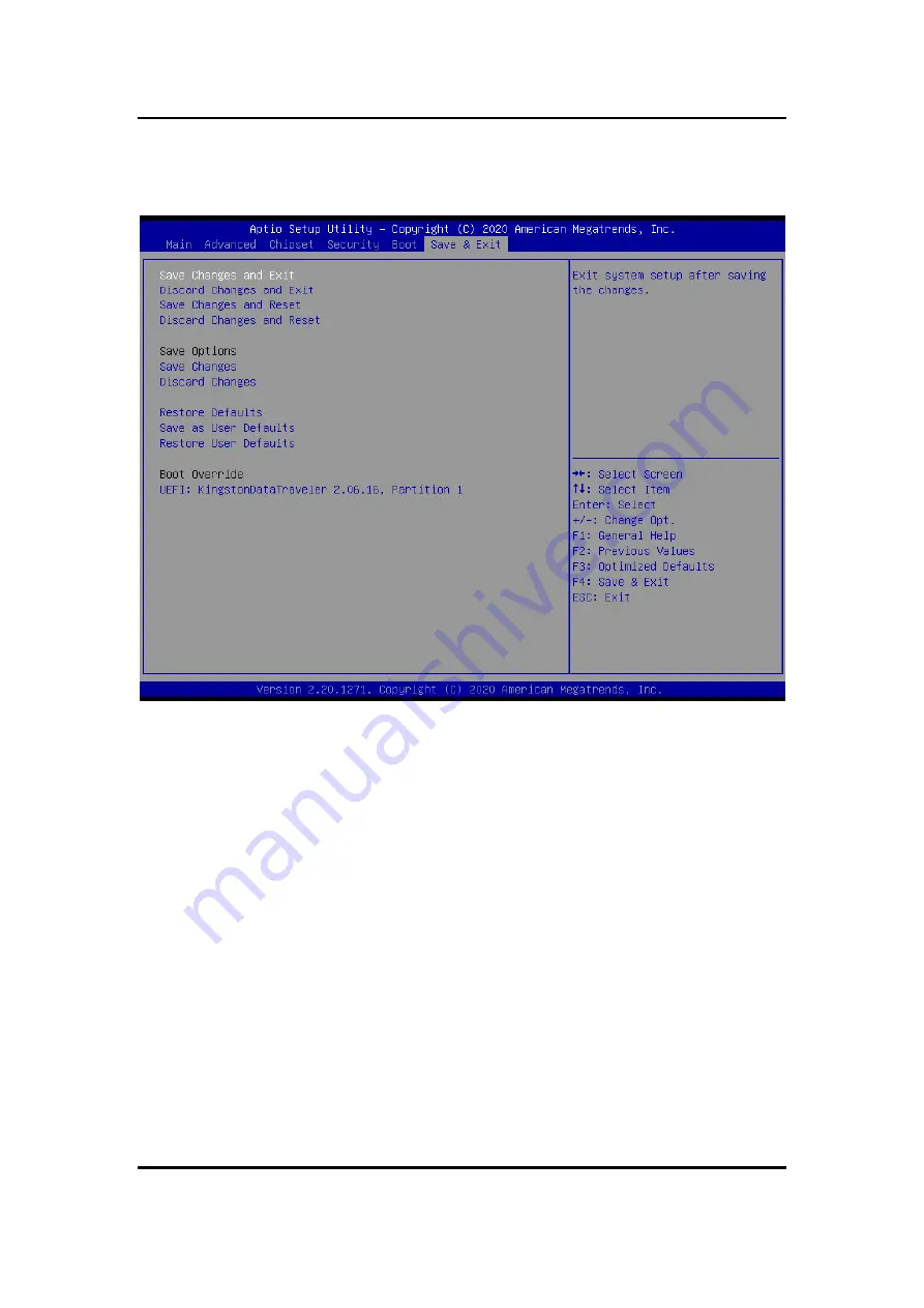
The  Save  &  Exit  menu  allows  users  to  load  system  configuration  with  optimal  or  fail-safe 
default values. 


Save Changes and Exit


When  users  have  completed  the  system  configuration  changes,  select  this  option  to  leave 
Setup  and  return  to  Main  Menu.  Select  Save  Changes  and  Exit  from  the  Save  &  Exit  menu 
and press <Enter>. Select Yes to save changes and exit.


Discard Changes and Exit


Select  this  option  to  quit  Setup  without  making  any  permanent  changes  to  the  system 
configurations  and  return  to  Main  Menu.  Select  Discard  Changes  and  Exit  from  the  Save  & 
Exit menu and press <Enter>. Select Yes to discard changes and exit.


Save Changes and Reset


When  completed  the  system  configuration  changes,  select  this  option  to  leave  Setup  and 
reboot the computer so the new system configurations take effect. Select Save Changes and 
Reset from the Save & Exit menu and press <Enter>. Select Yes to save changes and reset.


Discard Changes and Reset


Select  this  option  to  quit  Setup  without  making  any  permanent  changes  to  the  system 
configuration and reboot  the  computer.  Select  Discard  Changes  and  Reset from  the  Save  & 
Exit menu and press <Enter>. Select Yes to discard changes and reset.


Содержание eBOX640-521-FL Series

Страница 1: ...eBOX640 521 FL Series Embedded System User s Manual ...

Страница 2: ...or usefulness of any information in this document Axiomtek does not make any commitment to update any information in this manual Axiomtek reserves the right to change or revise this document and or product at any time without notice No part of this document may be reproduced stored in a retrieval system or transmitted in any forms or by any means electronic mechanical photocopying recording among ...

Страница 3: ...is correct before connecting it to any power outlet 5 Turn Off system power before cleaning Clean the system using a cloth only Do not spray any liquid cleaner directly onto the screen 6 Do not leave equipment in an uncontrolled environment where the storage temperature is below 40 or above 80 as it may damage the equipment 7 Do not open the system s back cover If opening the cover for maintenance...

Страница 4: ...on against electric shock not classified 2 Degree of protection against ingress of dust IP40 3 Equipment not suitable for use in the presence of a flammable anesthetic mixture with air oxygen or nitrous oxide 4 Mode of operation Continuous ...

Страница 5: ...ion to components requiring designated products for cleaning as mentioned below Cloth A piece of cloth is the best tool to use when rubbing up a component Although paper towels or tissues can be used on most hardware as well it is recommended to use a piece of cloth Water or rubbing alcohol A piece of cloth may be somewhat moistened with water or rubbing alcohol before being rubbed on the computer...

Страница 6: ...ademarks Acknowledgments Axiomtek is a trademark of Axiomtek Co Ltd IBM PC AT PS 2 VGA are trademarks of International Business Machines Corporation Intel and Pentium are registered trademarks of Intel Corporation MS DOS Microsoft C and QuickBasic are trademarks of Microsoft Corporation Windows 8 1 Windows 10 Linux and other brand names and trademarks are the properties and registered brands of th...

Страница 7: ...nstallation of the Express Mini Card 13 2 4 Installation of the 2 5 SATA Device 14 2 5 Installation of Flexible I O Modules 15 SECTION 3 JUMPER CONNECTOR SETTINGS 17 3 1 Locations of Jumpers Connectors 17 3 2 Summary of Jumper Settings 19 3 2 1 COM2 Data Power Select JP1 20 3 2 2 Audio JP2 20 3 2 3 Clear CMOS 20 3 2 4 AT ATX Power Mode Select JP6 20 3 3 Connectors 21 3 3 1 DC Jack Power Connector ...

Страница 8: ...g 31 4 2 Navigation Keys 31 4 3 Main Menu 32 4 4 Advanced Menu 33 4 5 Chipset Menu 44 4 6 Security Menu 49 4 7 Boot Menu 50 4 8 Save Exit Menu 51 APPENDIX A WATCHDOG TIMER 53 A 1 About Watchdog Timer 53 A 2 Sample Program 53 APPENDIX B TPM SETTINGS 55 APPENDIX C DIGITAL I O SETTINGS 65 ...

Страница 9: ...MM sockets for one channel DDR4 2400 MHz memory and enhanced system dependability through built in Watchdog Timer Features 1 LGA1151 socket 8th 9th gen Intel Core i7 i5 i3 Celeron processor CPU TDP max up to 35W 2 Supports 2 COM 6 USB and 8 CH DI DO 3 Front I O connectivity design 4 M 2 Key E for Wi Fi Reliable and Stable Design The embedded system supports LGA1151 socket 8th 9th gen Intel Core i7...

Страница 10: ... male connector COM1 select by BIOS One RS 232 9 pin D Sub male connector COM2 One HDMI with resolution max up to 3840 x 2160 30Hz One DisplayPort max up to 4096 x2 304 60Hz Two RJ 45 connectors for 10 100 1000 Base T Ethernet ports LAN1 1000 100 10Mbps Gigabit Fast Ethernet support Wake on LAN PXE with Intel i211AT LAN2 1000 100 10Mbps Gigabit Fast Ethernet PXE with Intel i219V Two USB 3 0 connec...

Страница 11: ...68 2 64 w SSD 3Grms STD random 5 500 Hz 1 hr axis Shock Vibration IEC 60068 2 27 w SSD 50G half sine 11 ms duration Weight 3 kg 6 61 lb without package 3 6 kg 7 94 lb with package Dimensions 195 mm 7 67 W x 210 3 mm 8 27 D x 80 mm 3 14 H 1 2 4 Driver CD Content Please download the following eBOX640 521 FL drivers from the Axiomtek official website Chipset Ethernet Graphic USB 3 0 Intel ME HD Audio...

Страница 12: ...eBOX640 521 FL Series User s Manual Introduction 4 1 3 Dimensions The following diagrams show dimensions and outlines of the eBOX640 521 FL 1 3 1 System Dimensions ...

Страница 13: ...eBOX640 521 FL Series User s Manual Introduction 5 1 3 2 Wall mount Bracket Dimensions ...

Страница 14: ...screws metric 3 x6 are required Step 2 Use the device with the wall mount plate attached as a guide to mark the correct locations of the four screws Step 3 Insert a Truss head screw thread diameter less than 4mm head through the middle of the keyhole shaped aperture on the plate and then slide the device downwards Tighten the screw head for added stability ...

Страница 15: ... Front View Side View 1 Power button 9 Line out 2 LEDs power HDD 10 HDMI port 3 LAN 1 11 Flexible IO Window default 2 x DB9 half cut bracket 4 AT ATX quick switch 12 COM 1 RS232 422 485 5 LAN 2 13 COM 2 RS232 6 DIO port 14 2 x USB 3 0 7 DisplayPort 15 4 x USB 2 0 8 2 x Antenna opening hole 16 DC Jack power input 17 2 x Antenna opening hole ...

Страница 16: ...em unit x 1 Screws pack x 1 Foot pad x 4 HDD bracket x 2 DRAM Thermal pad x 2 1 6 Model List eBOX640 521 FL DC Fanless embedded system with LGA1151 8th gen Intel Core i7 i5 i3 Celeron processor Intel H310 HDMI DisplayPort 6 USB 2 COM M 2 slot and 19VDC Please contact Axiomtek s distributors immediately in case any abovementioned items are missing ...

Страница 17: ...rd Step 2 Locate the four screws on the top heatsink used to fasten the heatsink to the chassis Step 3 Loosen these screws to remove the top heatsink Step 4 Remove the warning label and disengage load lever Disengage the load lever by pushing its hook down and then pulling it slightly outward Rotate the load lever to the open position at approximately 135 Rotate the load plate to the open position...

Страница 18: ...processor which aligns with connection 1 indicator chamfer on the socket and notice processor keying features that line up with posts along socket walls Grasp the processor with the thumb and index finger along the top and bottom edges The socket will have cutouts for your fingers to fit into Carefully place the processor into the socket body vertically Note Never touch the fragile socket contacts...

Страница 19: ...allation steps of the CPU processor Align pins of the CPU with pin holes of the socket Be careful of the CPU s orientation that users need to align the arrow mark on the CPU with the arrow key on the socket Step 7 Put the top cover and fasten all screws back onto the system ...

Страница 20: ... Step 3 Loosen the screws to remove the top heatsink and locate the two SO DIMM sockets on the main board Then place a thermal pad on the DRAM socket Please also put another DRAM thermal pad on top cover as red marked Step 4 Locate the memory module insert the gold colored contact into the socket and push the module down until it is locked in place by the two end latches Step 5 Put the top cover a...

Страница 21: ... cord Step 2 Turn the system upside down to locate the two screws at the rear side and then loosen the two screws Step 3 Locate the Express Mini Card slot within the red line marked Step 4 Slide the Mini Card into the Mini Card slot with caution and fasten the screw of the Express Mini Card Step 5 Assemble the bottom cover back and fasten all screws ...

Страница 22: ...2 Turn the system upside down to locate the two screws at the rear side and then loosen the two screws Step 3 Remove the bottom cover and locate the SSD HDD within the red line marked Step 4 Please prepare the following items to assemble SSD HDD and then fasten two screws to fix SSD HDD Step 5 Connect the SSD HDD directly and make sure the insertion is complete ...

Страница 23: ...sted below please refer to their respective quick manuals AX92902 LAN Module RJ45 1 AX92903 CAN Bus CAN Open Module DB9 1 AX92906 COM Module DB9 2 Step 1 Prepare the optional flexible I O kit as the below photo shows Step 2 Turn off the system and unplug the power cord Step 3 Loosen all screws to open the bottom cover and then insert the mPCIe module into one of the mPCIe slots Flexible IO window ...

Страница 24: ... Step 4 Assemble the I O cable to the I O bracket and then fasten the dual screws of the flexible I O Window to fix the I O bracket to the I O window Step 5 Connector the cable to the mini card slot Step 6 Fasten the bottom cover with all screws onto the system ...

Страница 25: ...SECTION 3 JUMPER CONNECTOR SETTINGS Proper jumper settings configure the eBOX640 521 FL to meet various application needs Hereby all jumpers settings along with their default settings are listed for devices onboard 3 1 Locations of Jumpers Connectors MANO521 Top Side ...

Страница 26: ...per Connector Settings 18 MANO521 Bottom Side Note It is strongly recommended that any unmentioned jumper settings should not be modified without instructions by Axiomtek FAEs Any modifications without instructions might cause system failure ...

Страница 27: ...ions Settings JP1 COM2 Data Power Select Default RS 232 Data CN27 Pin 1 DCD 3 5 Close CN27 Pin 8 RI 4 6 Close JP2 Audio Output Select Line out only 1 3 2 4 Close JP4 Clear CMOS Default Normal Operation 1 2 Close JP5 Case Open Select Default Close 1 2 Close JP6 AT ATX Power Mode for Quick SW Cable Select Default ATX Mode 1 2 Close Note How to setup Jumpers That a cap on a jumper is to close the jum...

Страница 28: ... 3 Move the jumper clip from pins 1 2 default to pins 2 3 Keep the clip on pins 2 3 for about 5 10 seconds then move the clip back to pins 1 2 4 Re install the battery 5 Plug the power cord and turn ON the computer 6 Hold down the Del key during the boot process and enter BIOS setup to re enter data 3 2 4 AT ATX Power Mode Select JP6 Use this Quick SW to select AT or ATX power mode Functions Setti...

Страница 29: ...he eBOX640 521 FL series External Connectors Sections DC Jack Power Connector CN1 3 3 1 USB 2 0 Stack connector CN2 3 3 2 USB 3 0 Connector CN3 3 3 3 Ethernet Connector CN4 CN5 3 3 4 COM1 D Sub Connector CN6 3 3 5 COM2 D Sub Connector CN27 3 3 6 DisplayPort and HDMI Connector CN8 3 3 7 Audio Jack Connector CN7 3 3 8 8 CH DIO Connector CN10 3 3 9 Internal Connectors Sections M 2 Key E Connector CN1...

Страница 30: ...therboard comes with one stacked Universal Serial Bus compliant with USB 2 0 connector on the rear I O for installing USB peripherals such as a keyboard mouse scanner etc 3 3 3 USB 3 0 Stack Port CN3 The motherboard comes with one stacked Universal Serial Bus compliant with USB 3 0 connector on the rear I O for installing USB peripherals such as a keyboard mouse scanner etc Pins Signals Pins Signa...

Страница 31: ...N5 LAN2 with Intel i219V Note Speed LED turns orange for 1000Mbps or green for 100Mbps Both CN4 and CN5 support Wake on LAN Pins 1000 Base T 100 10 Base T Descriptions L1 BI_DA TX Bidirectional or Transmit Data L2 BI_DA TX Bidirectional or Transmit Data L3 BI_DB RX Bidirectional or Receive Data L4 BI_DC N C Bidirectional or Not Connected L5 BI_DC N C Bidirectional or Not Connected L6 BI_DB RX Bidi...

Страница 32: ...422 485 are listed in table below 3 3 6 COM2 D Sub Connector CN27 This connector is a standard D Sub connector for COM2 serial port interface which is selectable for RS 232 mode by BIOS setting see section 4 4 The pin assignments of RS 232 are listed in table below Pins RS 232 RS 422 RS 485 1 DCD TX Data 2 RXD TX Data 3 TXD RX N C 4 DTR RX N C 5 GND GND GND 6 DSR N C N C 7 RTS N C N C 8 CTS N C N ...

Страница 33: ... Install audio driver and then attach audio devices to CN7 Pins Signals Pins Signals 1 DP_TX0_P 21 HDMI OUT_DATA2 2 GND 22 GND 3 DP_TX0_N 23 HDMI OUT_DATA2 4 DP_TX1_P 24 HDMI OUT_DATA1 5 GND 25 GND 6 DP_TX1_N 26 HDMI OUT_DATA1 7 DP_TX2_P 27 HDMI OUT_DATA0 8 GND 28 GND 9 DP_TX2_N 29 HDMI OUT_DATA0 10 DP_TX3_P 30 HDMI OUT_Clock 11 GND 31 GND 12 DP_TX3_N 32 HDMI OUT_Clock 13 GND 33 NC 14 GND 34 NC 15...

Страница 34: ...unction as input or output by software programming Note H or L means the default voltage is High or Low level and GPIO output is 5V Pin Description Digital I O 1 DIO0 GPI70 0xA06 Bit0 H 2 DIO1 GPI71 0xA06 Bit1 H 3 DIO2 GPI72 0xA06 Bit2 H 4 DIO3 GPI73 0xA06 Bit3 H 5 DIO4 GPI74 0xA06 Bit4 H 6 DIO5 GPI75 0xA06 Bit5 H 7 DIO6 GPI76 0xA06 Bit6 H 8 DIO7 GPI77 0xA06 Bit7 H 9 GND ...

Страница 35: ...K_DN 23 CNV_WR_CLK_DP 32 CNV_RGI_DT 34 CNV_RGI_RSP 33 GND 36 CNV_BRI_DT 35 PCIE12_TX_DP 38 CL_RST 37 PCIE12_TX_DN 40 CL_DATA 39 GND 42 CL_CLK 41 PCIE12_RX_DP 44 CNV_PA_BLANKING 43 PCIE12_RX_DN 46 CNV_MFUART2_TXD 45 GND 48 CNV_MFUART2_RXD 47 CLKOUT_PCIE_P3 50 PCH_SUSCLK 49 CLKOUT_PCIE_N3 52 BUF_PLT_RST 51 GND 54 BT_KILL1 53 NGFF_CLKREQ3 56 WLAN_KILL1 55 PCH_WAKE 58 N C 57 GND 60 N C 59 CNV_WT_1_DN ...

Страница 36: ...KREQ 8 UIM_PWR 9 GND 10 UIM_DAT 11 REFCLK 12 UIM_CLK 13 REFCLK 14 UIM_REST 15 GND 16 UIM_VPP 17 N C 18 GND 19 N C 20 3 3VAUX pull high R 21 GND 22 PERST 23 SATA0_RX_DP 24 3 3VAUX 25 SATA0_RX_DN 26 GND 27 GND 28 1 5V 29 GND 30 SMB_CLK 31 SATA0_TX_DN 32 SMB_DATA 33 SATA0_TX_DP 34 GND 35 GND 36 USB 9_D 37 GND 38 USB 9_D 39 3 3VAUX 40 GND 41 3 3VAUX 42 N C 43 GND 44 N C 45 N C 46 N C 47 N C 48 1 5V 49...

Страница 37: ...d 8 connect the case mounted speaker unit or internal buzzer While connecting the board to an internal buzzer please set pin 2 and 4 closed while connecting to an external speaker you need to set pins 2 and 4 opened and connect the speaker cable to pin 8 and pin 2 Power On Off Button Pin 9 and 10 connect the power button on the front panel to the board which allows users to turn on or off power su...

Страница 38: ...eBOX640 521 FL Series User s Manual Jumper Connector Settings 30 This page is intentionally left blank ...

Страница 39: ...navigation process These keys include F1 F2 Enter ESC Arrow keys and so on Note Some of the navigation keys differ from one screen to another Hot Keys Description Left Right The Left and Right Arrow keys allow users to select a setup screen Up Down The Up and Down Arrow keys allow users to select a setup screen or sub screen Plus Minus The Plus and Minus Arrow keys allow users to change the field ...

Страница 40: ...low The Main BIOS setup screen is also shown below BIOS Information Display the auto detected BIOS detail information System Date Time Use this option to change the system time and date Highlight System Time or System Date using the Arrow keys Enter new values through the keyboard Press the Tab key or the Arrow keys to move between fields The date must be entered in MM DD YY format The time is ent...

Страница 41: ... CPU and other system devices You can select any of the items in the left frame of the screen to go to the sub menus IT8625 Super IO Configurations Hardware monitor Trusted computing ACPI settings CPU Configuration SATA and RST Configuration PCH FW Configurations USB Configurations For items marked with please press Enter for more options ...

Страница 42: ...n use this screen to select options for the Super IO Configuration and change the value of the selected option A description of the selected item appears on the right side of the screen For items marked with Serial Port 1 2 Configuration Use these items to set parameters related to serial port 1 2 ...

Страница 43: ...eBOX640 521 FL Series User s Manual BIOS Setup Utility 35 ...

Страница 44: ...eBOX640 521 FL Series User s Manual BIOS Setup Utility 36 Hardware Monitor This screen monitors hardware health status ...

Страница 45: ...lity 37 Trust Computing This screen provides function for specifying the TPM settings Security Device Support Enable or disable BIOS support for security device OS will not show security device TCG EFI protocol and INT1A interface will not be available ...

Страница 46: ...Manual BIOS Setup Utility 38 TPM Device Selection Select TPM device dTPM External extended Infineon s TPM Pending operation Schedule an operation for the security device see image below None TPM Clear Clear all data secured by TPM ...

Страница 47: ...X640 521 FL Series User s Manual BIOS Setup Utility 39 ACPI Settings ACPI Sleep State When the suspend button is pressed the ACPI Advanced Configuration and Power Interface sleep state is S3 Suspend to RAM ...

Страница 48: ...ntel Virtualization Technology When enabled a VMM Virtual Machine Mode can utilize the additional hardware capabilities It allows a platform to run multiple operating systems and applications independently hence enabling a single computer system to work as several virtual systems Intel R SpeedStep tm Enable or disable Intel SpeedStep It allows more than two frequency ranges to be supported ...

Страница 49: ... up BIOS automatically detects the presence of SATA devices In the SATA Configuration menu you can see the currently installed hardware in the SATA ports SATA Controller s Enable or disable the SATA Controller feature The default is Enabled SATA Mode Selection Determine how SATA controller s operate ...

Страница 50: ...eBOX640 521 FL Series User s Manual BIOS Setup Utility 42 PCH HW This screen shows ME Firmware information ...

Страница 51: ...eBOX640 521 FL Series User s Manual BIOS Setup Utility 43 USB Configurations USB Devices Display all detected USB devices ...

Страница 52: ...Menu The Chipset menu allows users to change the advanced chipset settings Users can select any of the items in the left frame of the screen to go to the sub menus PCH IO Configuration System Agent SA Configuration For items marked with please press Enter for more options ...

Страница 53: ...reen allows users to configure System Agent SA parameters For items marked with please press Enter for more options Graphics Configuration Select to open sub menu for parameters related to graphics configuration Memory Configuration Select to open sub menu for information related to system memory ...

Страница 54: ...t the video device which will be activated during POST Power On Self Test The secondary boot display selection will appear based on your selection Secondary IGFX Boot Display After selecting other than AUTO on Primary IGFX Boot Display the Secondary IGFX Boot Display will show up and its options are DP and HDMI ...

Страница 55: ...eBOX640 521 FL Series User s Manual BIOS Setup Utility 47 Memory Configuration This screen shows the system memory information ...

Страница 56: ...eBOX640 521 FL Series User s Manual BIOS Setup Utility 48 PCH IO Configuration This screen allows you to set PCH parameters ...

Страница 57: ...ecurity menu allows users to change the security settings for the system Administrator Password This item indicates whether an administrator password has been set installed or uninstalled User Password This item indicates whether a user password has been set installed or uninstalled ...

Страница 58: ...boot options of the system Setup Prompt Timeout This item sets number of seconds to wait for setup activation key Options 1 Default Bootup NumLock State Use this item to select the power on state for the keyboard NumLock Quiet Boot Select to display either POST output messages or a splash screen during boot up ...

Страница 59: ...hanges to the system configurations and return to Main Menu Select Discard Changes and Exit from the Save Exit menu and press Enter Select Yes to discard changes and exit Save Changes and Reset When completed the system configuration changes select this option to leave Setup and reboot the computer so the new system configurations take effect Select Save Changes and Reset from the Save Exit menu a...

Страница 60: ...tore Defaults It automatically sets all Setup options to a complete set of default settings when users select this option Select Restore Defaults from the Save Exit menu and press Enter Save as User Defaults Select this option to save system configuration changes done so far as User Defaults Select Save as User Defaults from the Save Exit menu and press Enter Restore User Defaults It automatically...

Страница 61: ... The watchdog timer gives us solution The watchdog timer is a counter that triggers a system reset when it counts down to zero from a preset value The software starts counter with an initial value and must reset it periodically If the counter ever reaches zero which means the software has crashed the system will reboot A 2 Sample Program 1 Enter ADU and press F4 to select the superior ITE 2 PORT s...

Страница 62: ...eBOX640 521 FL Series User s Manual 54 Watchdog Timer This page is intentionally left blank ...

Страница 63: ...eBOX640 521 FL Series User s Manual TPM Settings 55 APPENDIX B TPM SETTINGS 1 Setup BitLocker Drive Encryption main storage Press Win R and type Control Panel then select BitLocker Drive Encryption ...

Страница 64: ...eBOX640 521 FL Series User s Manual 56 Digital I O Settings 2 Insert an external storage device for example USB Storage To back up BitLocker recovery key in a new file and save it to the USB Storage ...

Страница 65: ...eBOX640 521 FL Series User s Manual TPM Settings 57 3 Please follow the steps below to encrypt your storage device ...

Страница 66: ...eBOX640 521 FL Series User s Manual 58 Digital I O Settings Now the system prompts that the operating system drive encryption is in progress and the encryption progress is checked ...

Страница 67: ...eBOX640 521 FL Series User s Manual TPM Settings 59 Select and click the icon in the lower right corner to complete the encryption ...

Страница 68: ...eBOX640 521 FL Series User s Manual 60 Digital I O Settings 4 Confirm the completion of encryption ...

Страница 69: ...ngs 61 5 Disable TPM function in BIOS Setup Utility 6 When the system is powered on and you see the following screen it means the TPM module function is working fine Note that BitLocker cannot be executed if your system does not have TPM function ...

Страница 70: ...User s Manual 62 Digital I O Settings Note System with no TPM function support is demonstrated as below 1 TPM information is not found in Device Manager 2 When trying to turn on Bitlocker the following error message shows up ...

Страница 71: ...eBOX640 521 FL Series User s Manual TPM Settings 63 ...

Страница 72: ...eBOX640 521 FL Series User s Manual 64 Digital I O Settings This page is intentionally left blank ...

Страница 73: ...tput by software programming AP Programming Please download the DIO demo source code from AXIOMTEK website for programming AP Step 1 Run DIO_Demo exe Pins Descriptions Digital I O 1 DIO0 GPI70 0xA06 Bit0 H 2 DIO1 GPI71 0xA06 Bit1 H 3 DIO2 GPI72 0xA06 Bit2 H 4 DIO3 GPI73 0xA06 Bit3 H 5 DIO4 GPI74 0xA06 Bit4 H 6 DIO5 GPI75 0xA06 Bit5 H 7 DIO6 GPI76 0xA06 Bit6 H 8 DIO7 GPI77 0xA06 Bit7 H 9 GND ...

Страница 74: ...eBOX640 521 FL Series User s Manual 66 Digital I O Settings Step 2 setup input or output Step 3 Read status of input Setup low high level of output ...

Отзывы: