MC13192U Transceiver Module
User Guide
4
Standard installation places module at 90 degrees vertical to controller or host platform.
Versatile connection to host controller boards will allow stacking in different
configurations or connection by ribbon cable, contact Axiom with special requirements.
Module applies an embedded antenna and derives the 3.3V to 5.5V DC input power
from the supporting host platform so no other accessories are required. Mounting holes
are provided opposite from the connector to secure the module if required, 4-40 size
nylon or plastic hardware should be applied for this purpose.
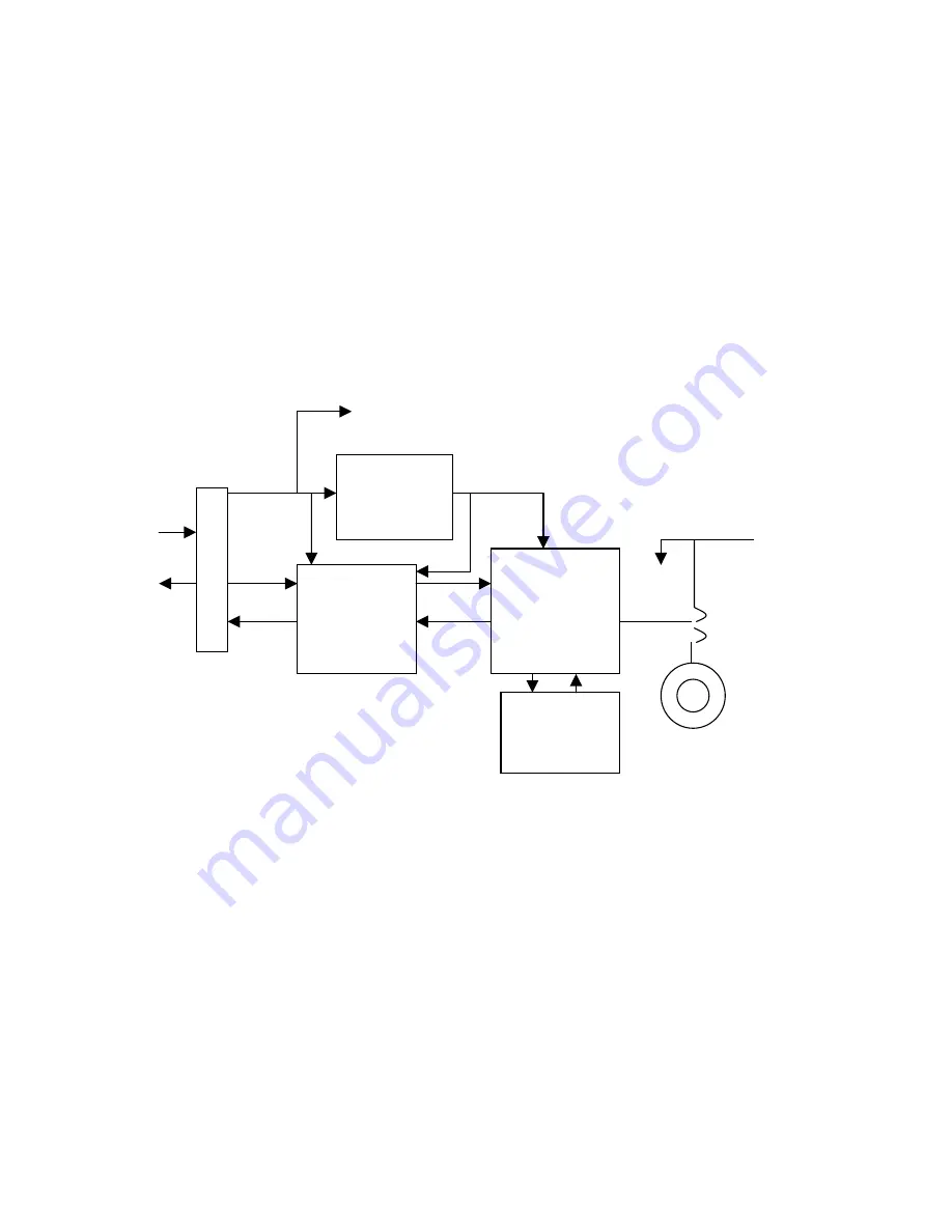
Module Block Diagram
Host
Operational Description
The MC13192U provides an IEEE802.15.4 capable transceiver when operated
correctly. Transceiver operation is 2.4Ghz ISM band with 250Kbits a second O-QPSK
modulation and spread spectrum encoding. Module is interfaced to the host controller
by the Serial Peripheral Interface (SPI) synchronous serial bus for command and data
transfer. Other 3 or 4 wire synchronous serial bus type are compatible also. Individual
control and status signals are applied by the host controller’s general purpose I/O ports,
refer to the connection charts for more details. Module power is derived from the host
controller also. The supporting controller’s regulated power supply should be able to
provide the 60ma required for module operation.
Host 3.3 –
5.5VDC
Input
3.0VDC
regulated
supply
MC13192
2.4GHz RF
Transceiver
Signal I/O
Buffer &
level
translator
J1 or J2
Connector
Embedded
“F” Antenna
J104 Test
Jack
Antenna
select –
Hardwired
at factory
VDD indicator
16Mhz
reference
crystal


