background image


3603 Burron Avenue, Saskatoon, SK S7P 0E4    Ph: (306) 651-1815    Fax: (306) 651-2293 

email: [email protected]    website: www.axiomind.com


DMF Series Solution Feeder


Installation, Operation, & Maintenance Instructions 


-


Français page 11 - 


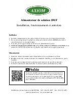
Installation Procedure 

 
1)


Set system feeder on a secure and level base or on the provided wall bracket.  

2)


If mounting on the wall, the cardboard cut-out on the side of the DMF box may be used to locate the 
screw holes for the wall bracket.  

3)


Ensure the wall bracket is level and fastened securely to the wall.  

4)


HANG AND FILL TANK PRIOR TO MAKING SYSTEM CONNECTION.

 This helps to 

ensure that the tank is securely seated on the mounting bracket


Startup Procedure 


1)


Close isolation valve between feeder and system connection point 

2)


Fill reservoir, turn valve on feeder to mix/purge and plug in 

3)


Ensure pump is cycling fluid through reservoir (primed) 

4)


Simultaneously turn valve to run and open isolation valve to system 


Scan the QR code to the left, search for Axiom Industries Ltd. on 
YouTube, or use the link below to view a list of instructional 
videos on the DMF series system feeders: 
https://www.youtube.com/watch?v=tmWsw0clEng&list=UU3IhT
10cEPKmm_S-HlGcbNw


Содержание DMF Series

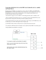
Страница 1: ...vel and fastened securely to the wall 4 HANG AND FILL TANK PRIOR TO MAKING SYSTEM CONNECTION This helps to ensure that the tank is securely seated on the mounting bracket Startup Procedure 1 Close isolation valve between feeder and system connection point 2 Fill reservoir turn valve on feeder to mix purge and plug in 3 Ensure pump is cycling fluid through reservoir primed 4 Simultaneously turn val...

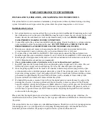
Страница 2: ...position 7 Insert DC plug into the System Feeder first and then plug power supply into 120v outlet The red LED in the power supply cord should light up If it does not check the power receptacle 8 Once the pump is primed turn the feeder valve handle to horizontal position run position open system isolation valve and allow pump to pressurize system If the system pressure is below the cut in pressure...

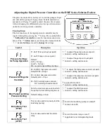
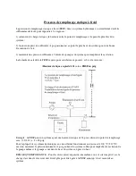
Страница 3: ... psi Min recommended differential 2psi to adjust the pump cut out set point to lock in setting and move on to adjust the pump cut in set point to lock in setting and move on Pressure Settings for the Alarm F2 H HiAL high pressure alarm Default HiAL 26 psi F2 L LoAL low pressure alarm Default LoAL 10 psi F2 r NO normally open contacts NC normally closed contacts to adjust the high pressure alarm se...

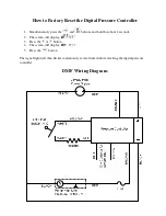
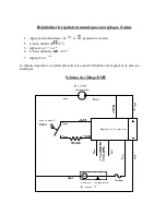
Страница 4: ...ress the and buttons and hold for about 4 seconds 2 The screen will display 3 Press the or button 4 The screen will display 5 Press the button The signal light will then flicker continuously several times before resetting the digital pressure controller DMF Wiring Diagram ...

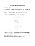
Страница 5: ...for calculating the required CSFP to satisfy points 1 2 is Static height in feet 2 31 4 CSFP in psig As an example the CSFP for a system with a static height above the fill point of 32 feet would be 32 2 31 4 18 psig For most closed hydronic systems operating below about 210 F maintaining the minimum top of system pressure at 4 psig will be adequate to prevent pump cavitation even if the pumps are...

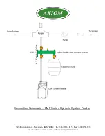
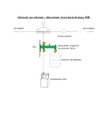
Страница 6: ...3603 Burron Avenue Saskatoon SK S7P 0E4 Ph 306 651 1815 Fax 306 651 2293 email sales axiomind com website www axiomind com Connection Schematic DMF Series Hydronic System Feeder ...

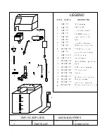
Страница 7: ...stic manifold block tank lid MF DMF 0950 DMF 3400 DMF150 4050 DMF 3100 DMF 3350 DMF 3000 DMF 3050 DMF 3250 16 DMF150 4000 DMF 3200 DMF 3500 3 8 PVC suction hose 4 6 US gal tank large cable clamp for wires strainer 120V to 24DCV power adapter 3 8 PE hose for mix valve plastc clamp for suction hose pump motor assembly tank cap MF DMF 0102 MF DMF 0930 MF DMF 0920 MF DMF 1200 MF DMF 1520 MF DMF 1000A ...

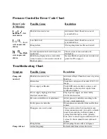
Страница 8: ...d Check for cause of system fluid loss Blown fuse Check fuse and replace if needed 250V 2 0 Amps Power supply or Breaker Check LED indicator light on power cord flip breaker or obtain power supply from reseller and replace Power supply unplugged or loose electrical connections Plug in power supply or correct faulty electrical connection Pressure controller out of adjustment Adjust pressure control...

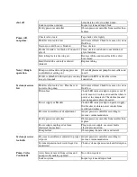
Страница 9: ...ut power to the pump Add correct fluid Check for cause of system fluid loss Blown fuse Check LED indicator light on power cord If not lit ensure it is plugged in and that there is power at the receptacle Check fuse located near pump and replace if needed Power supply or Breaker Check LED indicator light on power supply flip breaker or obtain power supply from reseller and replace Pressure controll...

Страница 10: ...anel and tie them to terminals 1 and 2 2 Press and hold the function button to gain access to the functions menu Select F2 R NO NC and use the arrow buttons to choose NO or NC then press FCN to confirm the selection 3 Tap the Function button again until you get to F5 alarm test relay and press the ON OFF button to turn the alarm relay on or off Press FCN again to finish testing the relay 4 Connect...

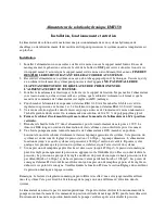
Страница 11: ...age Mise en marche 1 Fermer le robinet d isolement entre l alimentateur et le raccordement au système 2 Remplir le réservoir tourner la manette de commande à Mix Purge sur l alimentateur puis le brancher 3 S assurer que la pompe refoule la solution à partir du réservoir qu elle est amorcée 4 Tourner la manette de commande à Run et ouvrir le robinet d isolement du système 3603 Burron Avenue Saskato...

Страница 12: ...entateur à Mix position verticale 7 Brancher d abord la fiche CC dans l alimentateur puis le transformateur dans la prise à 120 V Le témoin à DEL rouge du cordon d alimentation devrait s allumer sinon vérifier la prise de courant 8 Une fois la pompe amorcée tourner la manette de l alimentateur à RUN marche en position horizontale ouvrir le robinet d isolement et laisser la pompe pressuriser le sys...

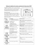
Страница 13: ...yer sur pour confirmer et passer au réglage suivant pour régler le point de consigne de basse pression Appuyer sur pour confirmer et passer au réglage suivant Réglages de pression pour l alarme F2 H HiAL règle l alarme haute pression Valeur par défaut 26 psi F2 L LoAL règle l alarme de basse pression Valeur par défaut 10 psi F2 R Contacts NO normalement ouvert ou NC normalement fermé pour modifier...

Страница 14: ... usine 1 Appuyez simultanément sur et pendant 4 secondes 2 L écran affiche 3 Appuyez sur ou 4 L écran affichera 5 Appuyez sur Le témoin clignotera en continu plusieurs fois avant de réinitialiser le régulateur de pression numérique Schéma de câblage DMF ...

Страница 15: ...de calcul de la PRSF requise pour satisfaire aux points 1 et 2 est la suivante Hauteur statique en pieds 2 31 4 PRSF en psig Exemple la PRSF pour un système ayant une hauteur statique de 32 pi au dessus du point de remplissage sera 32 2 31 4 18 psig Pour la plupart des systèmes hydroniques en circuit fermé fonctionnant au dessous de 100 C 210 F environ maintenir la pression minimale à 4 psig au ha...

Страница 16: ...Schéma de raccordement Alimentateur de système hydronique DMF ...

Страница 17: ......

Страница 18: ...uide dans le réservoir est bas Ajouter du fluide Vérifier la cause de la perte de fluide dans le système Fusible grillé Vérifier le fusible et remplacer si nécessaire 250 V 2 A Alimentation électrique ou disjoncteur Vérifier le témoin DEL sur le cordon d alimentation basculer le disjoncteur ou obtenir le transformateur auprès du revendeur et le remplacer Débranchement électrique ou connexions lâch...

Страница 19: ...d alimentation Vérifier le fusible situé près de la pompe et remplacer si nécessaire Alimentation électrique ou disjoncteur Vérifier le témoin DEL sur le cordon d alimentation basculer le disjoncteur ou obtenir le transformateur auprès du revendeur et le remplacer Pressostat mal réglé Régler le régulateur de pression selon les directives du fabricant Pressostat défectueux Obtenir un régulateur de ...

Страница 20: ... pour accéder au menu Sélectionner F2 R NO NC et utiliser les flèches Haut ou Bas pour choisir Normalement Ouvert NO ou Normalement Fermé NC puis appuyer sur FCN pour sauvegarder 3 Appuyer à nouveau sur le bouton FCN jusqu à atteindre F5 relais de test d alarme et appuyer sur le bouton ON OFF pour activer ou désactiver le relais d alarme Appuyer à nouveau sur FCN pour terminer le test du relais 4 ...

Отзывы: