Page 24
6.8
I2C
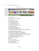
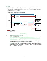
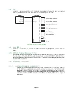
Ultra96-V1 supports one I2C bus. A TI TCA9544A Low-Voltage 8-Channel I2C Switch is specified
to isolate the I2C sub-buses from each other. All I2C buses operate at 1.80V.
ZU3EG
TCA9548A
SDA
SCL
RESET_B
SD0
SC0
SD1
SC1
SD2
SC2
SD3
SC3
SD4
SC4
SD5
SC5
SD6
SC6
SD7
SC7
A0
A1
A2
I2C0 – Low Speed Expansion
I2C1 – Low Speed Expansion
I2C2 – High Speed Expansion
I2C3 – High Speed Expansion
Power Regulator
INA226 Current Sense
n/c
I2C0_SDA
I2C0_SCL
PS_MIO12
USB Hub
Figure 4 – MPSoC I2C to I2C Switch
6.9
User LEDs
Ultra96-V1 provides four user-controllable LEDs connected to PS_MIO[17..20]. All User LEDs are
green.
6.10 MPSoC Thermal Bracket with Fan
The Ultra96-V1 uses a thermal bracket with fan for the MPSoC device. The bracket is mounted to
the bottom side of the Ultra96-V1 to help dissipate heat. A Sunon MC30060V1-000U-A99 fan is
used, connected to 5V and GND at J18 and J19. Users can control the fan using signal FAN_PWM
from PL IO F4 on Bank 65.
6.11 Expansion Connectors
6.11.1
Low Speed Expansion Connector (J7)
Ultra96-V1 provides a 96Boards compatible Low Speed Expansion Connector. A Molex
87381-4063 (or compatible) 40 pin low profile female 2mm receptacle (20x2) 4.5mm height
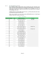
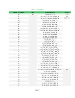
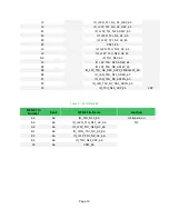
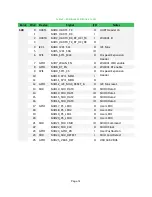
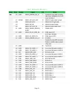
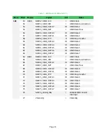
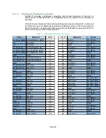
is specified. Table 13 shows the pinout of the Low Speed Expansion Header (Ultra96-V1
column) and the differences from the 96Boards specification (96Boards column). With the
exception of I2C0 and I2C1, all dedicated interfaces specified by 96Boards are replaced
with GPIO.

