


Page 22
6.4
USB
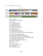
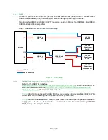
Ultra96-V1 provides one upstream (device) and two downstream (host) USB 3.0 connections. A
USB 2.0 downstream (host) interface is provided on the high speed expansion bus.
Two Microchip USB3320 USB 2.0 ULPI Transceivers and one Microchip USB5744 4-Port SS/HS
USB Controller Hub are specified.
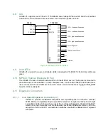
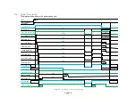
Figure 3 below shows the Ultra96-V1 USB Setup.
USB 3.0
Downstream
Port A
USB 3.0
Downstream
Port B
USB 2.0
Downstream
Expansion Port
USB 3.0 Hub
USB5744
USB 3.0
Upstream
USB 3.0
Upstream
ULPI Phy
USB3320
ULPI Phy
USB3320
ZU3EG
UPLI0
ULPI1
GTR0
GTR1
USB 3.0 Connection
USB 2.0 Connecttion
Figure 3 – USB Setup
6.4.1
USB5744 Implementation Details
Refer to the USB5744 datasheet
(
http://ww1.microchip.com/downloads/en/DeviceDoc/00001855C.pdf
) and the EVB-USB5744
Evaluation Board schematics (
http://ww1.microchip.com/downloads/en/DeviceDoc/EVB-
) for implementation details.
NOTE:
USB 3.0 Downstream Port A/B VUBS is controlled by a Microchip/Micrel MIC2009YML
USB Power Switch following the Evaluation Board implementation
NOTE:
USB2.0 Downstream Port VBUS is provided by the Low Speed Expansion Header 5V
supply (see 6.11.1). A Power switch is not required and the corresponding USB5744
PRT_CTLx pin for that port is left n/c.


