background image

Chapter 1: Introduction

3

About This Guide

This guide provides a basic overview of the 
HD I/O features and functionality.

For hardware installation instructions for your 
HD Native hardware, see the 

HD Native Install 

Guide

.

For hardware installation instructions for your 
Pro Tools|HD hardware, see the 

Pro Tools|HD 

User Guide

For Pro Tools installation instructions, see the 

Pro Tools Installation Guide

.

For additional information about using 
Pro Tools software, see the 

Pro Tools Reference 

Guide

 (in Pro Tools, choose 

Help > Pro Tools 

Reference Guide

).

Conventions Used in This Guide

All of our guides use the following conventions 
to indicate menu choices and key commands:

:

The names of 

Commands

Options

, and 

Settings


that appear on-screen are in a different font.

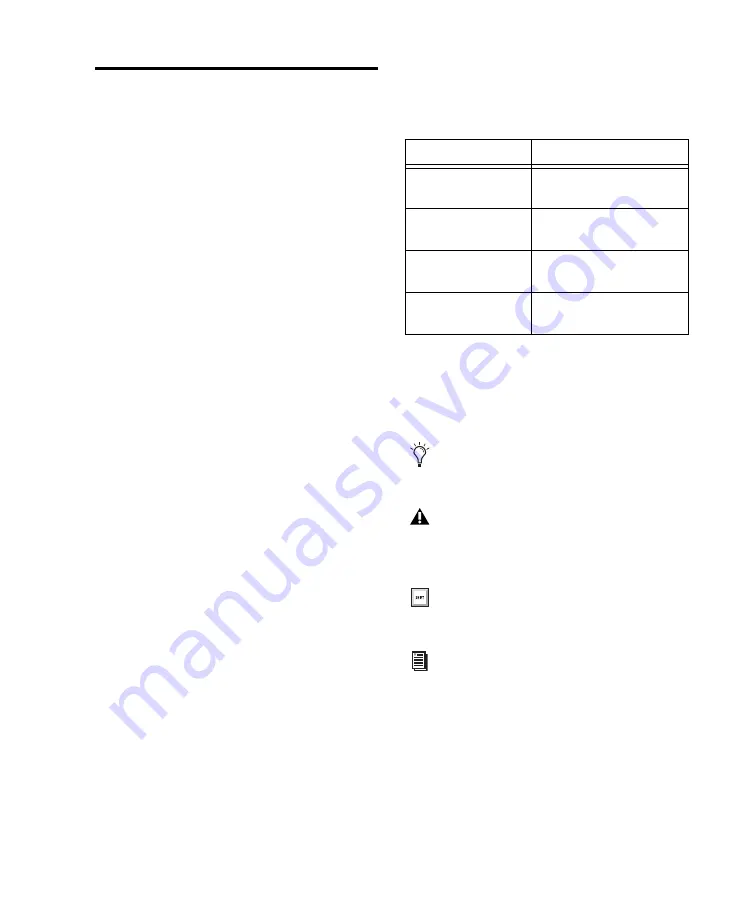
The following symbols are used to highlight 
important information:

Convention

Action

File > Save

Choose Save from the 
File menu

N

Hold down the Control key 
and press the N key

Control-click

Hold down the Control key 
and click the mouse button

Right-click 

Click with the right 
mouse button

User Tips are helpful hints for getting the 
most from your system.

Important Notices include information that 
could affect your data or the performance of 
your system.

Shortcuts show you useful keyboard or 
mouse shortcuts.

Cross References point to related sections in 
this guide and other Pro Tools guides.

Содержание HD I/O

Страница 1: ...HD I O Guide...

Страница 2: ...MediaComposer MIDI I O MIX MultiShell Nitris OMF OMF Interchange PRE ProControl Pro Tools M Powered Pro Tools Pro Tools HD Pro Tools LE QuickPunch Recti Fi Reel Tape Reso Reverb One ReVibe RTAS Sibel...

Страница 3: ...D I O 13 Connecting HD I O to HD Native Cards 14 Connecting HD I O to Pro Tools HD Cards 16 Chapter 4 Configuring HD I O in Pro Tools 19 Hardware Setup 19 Configuring HD I O 21 Using Input Trims 28 Ch...

Страница 4: ...tion Mode Instructions 39 About Calibration 39 Calibrating the HD I O 40 Switching Jumpers on the Analog Output Card 42 Appendix A Compliance Information 43 Environmental Compliance 43 EMC Electromagn...

Страница 5: ...96 kHz 176 4 kHz and 192 kHz with Analog In and Analog Out HD I O cards Soft Clip and Curv limiting circuits to protect against clipping on analog input Digital I O Up to 16 channels of 24 bit digita...

Страница 6: ...ed and approved For complete system requirements and a list of qualified computers operating systems hard drives and third party devices visit www avid com compatibility Registration Review the enclos...

Страница 7: ...l of our guides use the following conventions to indicate menu choices and key commands The names of Commands Options and Settings that appear on screen are in a different font The following symbols a...

Страница 8: ...e latest online manuals browse the Compatibility documents for system re quirements search the online Knowledge Base or join the worldwide Pro Tools community on the User Conference Training and Educa...

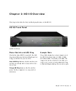
Страница 9: ...een LED Ring Indicates that the unit has pow ered up successfully and is connected to an ac tive system Orange LED Ring Indicates that the unit has power but the computer it is connected to is shut do...

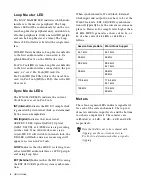
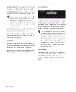
Страница 10: ...stem clock If no valid clock source is de tected HD I O will switch to internal clock the DIG LED will flash and an error message will appear on screen in Pro Tools LOOP Indicates that the HD I O is s...

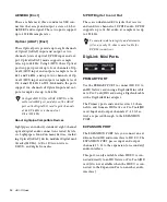
Страница 11: ...can add even more I O capacity up to a maximum possible 110 inputs and outputs See Chapter 5 Adding or Removing I O Cards Analog Input The HD I O Analog In card contains connectors for analog audio i...

Страница 12: ...ms for eight channels of analog audio output These balanced outputs operate at 4 dBu levels See Chapter 6 Pinout Diagrams for the DB 25 Connectors Output Trims The Output Trims below the DB 25 connect...

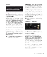
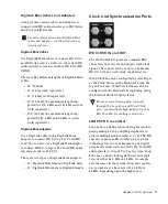
Страница 13: ...ith real time sample rate conversion on input only Note that Optical S PDIF is not supported with the Digital I O card and is supported with the enclosed Optical ports only for more informa tion see O...

Страница 14: ...PDIF Digital In and Out These are unbalanced RCA jacks that receive and send two channels of S PDIF audio S PDIF supports up to 24 bit audio at sample rates up to 192 kHz DigiLink Mini Ports PRIMARY...

Страница 15: ...CLOCK IN and OUT The Word Clock I O ports are standard BNC connectors that receive and output word clock signal These ports can be used to synchronize HD I O with any word clock capable device Word C...

Страница 16: ...ple Pro Tools HD peripherals together such as Pro Tools HD audio interfaces and SYNC HD AC Power This connector accepts a standard AC power ca ble HD I O is auto power selecting 100V to 240V and will...

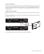
Страница 17: ...DigiLink Mini adapter You can add additional HD audio inter faces to your system using the Expansion port on the back of HD I O or using additional Pro Tools HD cards See Connecting HD I O to Pro Tool...

Страница 18: ...ni cable 2 Connect the additional HD I O or other compatible Pro Tools audio interface by doing one of the following Connect the Primary Port of the secondary interface to the Expansion Port of the pr...

Страница 19: ...he SYNC HD Guide For an example of connecting multiple Avid HD audio interfaces see Figure 2 below To make Loop Sync connections 1 Connect the Loop Sync Out of each interface to the Loop Sync In of th...

Страница 20: ...ble included with your Pro Tools HD system and a DigiLink to DigiLink Mini adapter 2 Do one of the following Connect the Primary Port of the second HD I O to the Expansion Port on the first HD I O wit...

Страница 21: ...s see Figure 4 below To make Loop Sync connections 1 Connect daisy chain the Loop Sync Out of each interface to the Loop Sync In of the next interface with a BNC cable 2 Connect the Loop Sync Out of t...

Страница 22: ...HD I O Guide 18...

Страница 23: ...te setting appears as the default sample rate when you create a new session This setting is available in the Hardware Setup dialog only when no session is open To change the default Sample Rate for ne...

Страница 24: ...common signal Depending on your audio interface configuration and the selected sample rate external options can include S PDIF Encl at all sample rates Optical S PDIF Encl up to 96 kHz AES EBU Encl at...

Страница 25: ...etup dialog This il luminates all the LEDs on the front panel of the selected audio interface 4 Make a note of which interface in your studio setup corresponds to the identified interface 5 Repeat the...

Страница 26: ...ut in multiple I O formats including analog AES EBU ADAT Op tical S MUX S PDIF and TDIF The Main page of the Hardware Setup dialog is where you define which physical inputs and out puts on your audio...

Страница 27: ...onal AES EBU I O ports on the optional card are listed as AES EBU 9 10 AES EBU 11 12 AES EBU 13 14 and AES EBU 15 16 Digital Format Select from the following digital input formats for the built in dig...

Страница 28: ...dBV Balanced DB 25 Analog Input port on the card Limiter HD I O provides options for soft limiting on each of the available analog input channels Se lect the desired option from the corresponding Lim...

Страница 29: ...or responding physical inputs on the HD I O Digi tal card If no HD I O Digital Expansion card is installed these tabs are not available Digital Format Select from the following digital formats for the...

Страница 30: ...AT 9 16 for the second card if pres ent At sample rates of 88 2 kHz and higher two ADAT options are available SRC and S MUX ADAT 1 8 Enable this option for eight channels of ADAT input This is the onl...

Страница 31: ...nabled automatically for all in put channels ADAT S MUX At sample rate higher than 48 kHz with ADAT S MUX selected as the Digital Format Sample Rate Conversion can be enabled or disabled for all input...

Страница 32: ...ing the Input Trims Consider the following when connecting a mixer If your mixer cannot handle more than 1 5V RMS inputs at 4 dBu then you should set the HD I O to operate at 10 dBV line level If your...

Страница 33: ...ent studio setups If you remove any of the cards from the HD I O the unit will continue to function as long as at least one card is installed albeit with reduced I O capabilities Removing an I O Card...

Страница 34: ...u removed from the I O card 11 Replace the top cover on the HD I O 12 Replace the original screws Hardware Setup Changes After Removing a Card In this case the Hardware Setup dialog will re flect the...

Страница 35: ...y installed I O card that you want to replace see Removing an I O Card on page 29 6 Look into the empty bay to locate the guide rails for the card to slide in on 7 Remove the Expansion I O card that y...

Страница 36: ...t connects the I O card to the HD I O chassis This ridge is only on one side of the connector and there is a matching groove on only one side of the 50 pin connector on the card 14 Gently push the cab...

Страница 37: ...e original three cards a second Analog Input tab will appear in the Hardware Setup dialog You can route these new inputs which will in this case be called Analog Inputs 9 16 with the same controls and...

Страница 38: ...HD I O Guide 34...

Страница 39: ..._HOT CH6_GND CH5_GND CH5_HOT CH5_COLD CH8_GND NC_1 CH1_GND CH2_HOT CH8_HOT MH1 1 8 7 6 5 4 3 2 27 12 24 11 23 22 21 9 8 7 20 14 3 15 16 17 4 5 19 18 6 2 13 25 10 1 26 4 Analog Outputs MH2 CH1_COLD CH1...

Страница 40: ...0 14 3 15 16 17 4 5 19 18 6 2 13 25 10 1 26 MH2 CH12_RCV_COLD CH12_RCV_HOT CH34_RCV_GND CH34_RCV_COLD CH56_RCV_GND CH56_RCV_HOT CH56_RCV_COLD CH78_RCV_GND CH78_RCV_HOT CH78_RCV_COLD CH78_XMT_COLD CH56...

Страница 41: ...GND4 GND6 GND5 CH34_XMT_DATA XMT_FS1 RCV_FS0 RCV_FS1 XMT_LRCK RCV_LRCK RCV_EMPHASIS CH56_XMT_DATA GND7 XMT_FS0 CH34_RCV_DATA GND2 XMT_EMPHASIS MH1 DB25F_RA_TDIF GND1 CH78_XMT_DATA GND8 GND9 7 8 CLK C...

Страница 42: ...HD I O Guide 38...

Страница 43: ...l scale dig ital clipping level Headroom The concept of headroom is slightly different for analog and digital devices Analog Most analog devices allow for a certain amount of headroom above 0 VU If yo...

Страница 44: ...Signal Generator plug in on the track 7 Set the Signal Generator plug in output level This should be the same value you entered as the Calibration Reference Level such as 18 dB 8 Set the Signal Genera...

Страница 45: ...h Auxiliary Input track receiving an external input signal now displays the reference level coming from the calibrated output default is 18 dB 3 Adjust the HD I O input level trim pots with the same s...

Страница 46: ...ch the jumpers for output channels on an Output card 1 Remove the Output card from the HD I O chas sis as described in Chapter 5 Adding or Re moving I O Cards 2 Place the card on a stable static free...

Страница 47: ...help conserve natural resources and ensure that it is recycled in a manner that protects human health and the environment For more information about where you can drop off your waste equipment for re...

Страница 48: ...ent thereby declaring conformity to EMC Directive 2004 108 EC and Low Voltage Directive 2006 95 EC Korean EMC Regulations Communication Statement Note This equipment has been tested and found to compl...

Страница 49: ...receptacles and the point where they exit from the equipment 11 Only use attachments accessories specified by the manufacturer 12 For products that are not rack mountable Use only with a cart stand tr...

Страница 50: ...HD I O Guide 46...

Страница 51: ......

Страница 52: ...ro Serra Boulevard Daly City CA 94014 3886 USA Technical Support USA Visit the Online Support Center at www avid com support Product Information For company and product information visit us on the web...

Отзывы: