background image

www.avenview.com 


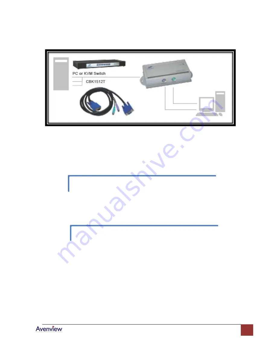
Installation Diagram of KVM-C5-S Transmitter 

c.


Function Test: 

Power ON your PC, the Transmitter will take the power from the PC’s PS/2 

connection. The front “PC ON” LED of the Transmitter will keep blinking 

Green

 to indicate 

the unconnected status of System Link. The LEDs above RJ45 will turn ON to indicate the 
activation of Video Signal.   


-


KVM-C5-R Receiver Installation 

a.


Site Selection:

 Place KVM-C5-R Receiver in an appropriate place.   


Cable Selection:

 For best VGA signal, use Cat 5e or Cat 6 cable. 

b.


Power ON:

 Plug power adapter to the Receiver and connect Keyboard / Video / Mouse to 

Receiver. The LEDs of unit should keep blinking to indicate the unconnected status of the 
cable. 


Test the functionality of the monitor and ensure that Keyboard and Mouse are working 
properly to finish the installation of the Transmitter. 

You can use magnetic pad to attach the unit on a metal plane or use attachable Rack 
Mounting Kit to fix the unit on selected area by screw. 

Содержание KVM-C5 Series

Страница 1: ...any form without the express written permission of Avenview Inc is strictly prohibited Disclaimer While every precaution has been taken in the preparation of this document Avenview Inc assumes no lia...

Страница 2: ...of Contents Getting Started 3 Key Features 3 Panel Description 4 Transmitter KVM C5 S and Receiver KVM C5 R 4 Installation and Operation 5 VGA C5 S Transmitter Installation 5 KVM C5 R Receiver Install...

Страница 3: ...using a USB to PS 2 converter to extend a USB interface computer Ex SUN Mac The KVM Extender is designed not only to provide accurate KVM signal but also easy to install It provides a magnetic pad and...

Страница 4: ...www avenview com 4 Panel Description Transmitter KVM C5 S and Receiver KVM C5 R...

Страница 5: ...t attached with Rack Mounting Kit b Device Connection Connect Keyboard Video Mouse to Transmitter Use 15 Pin Integrated 3 in 1 KVM Cable and connect the 15 Pin end to the Transmitter and other end of...

Страница 6: ...a Site Selection Place KVM C5 R Receiver in an appropriate place Cable Selection For best VGA signal use Cat 5e or Cat 6 cable b Power ON Plug power adapter to the Receiver and connect Keyboard Video...

Страница 7: ...er c Connect Cable Plug two ends of Cat 5 5e 6 cable to Transmitter and Receiver s RJ45 SYSTEM LINK ports Now the LEDs above RJ45 should turn on to indicate the activation of Video Signal and correct...

Страница 8: ...tings and Monitor tabs in your Display Properties dialog Off Center Screen Image Odd Colors or No Picture Try adjusting the brightness sharpness contrast and color balance controls of your monitor Try...

Страница 9: ...e Video D Sub 15 Female To PC KVM Switch Integrated D Sub 15 pin KVM Cable System Link RJ45 LED Display Status H Sync V Sync Max Resolution Distance 2048x1536 300m 1000 ft Power Consumption PS 2 AC 7...

Страница 10: ...www avenview com 10...

Отзывы: