


www.avenview.com
Page 7
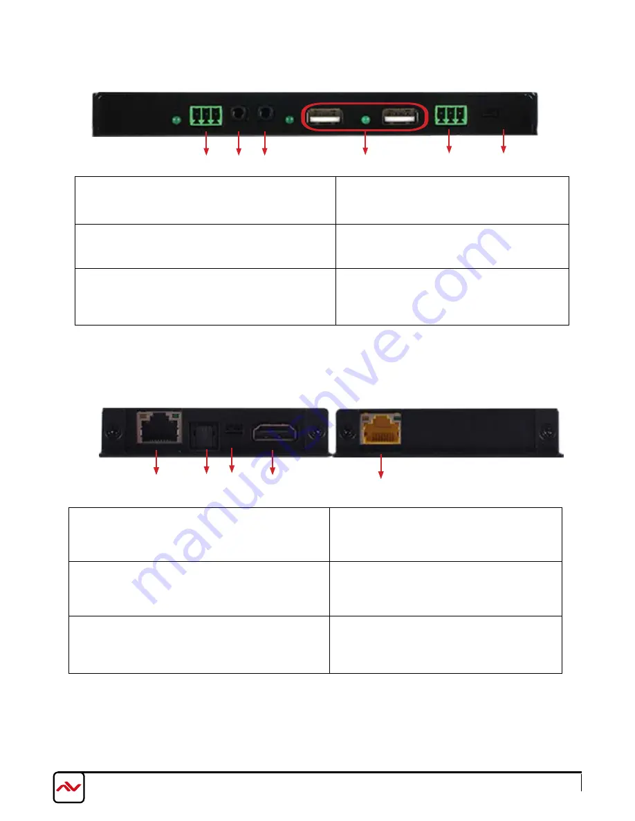
2.4.3 Input Panel (Receiver,
HBT2-C6POH-USB-
R) Front
2.4.4 Input Panel (Receiver,
HBT2-C6POH-USB
-R)
Side
3
2
4
5
1
6
8
7
10
11
9
1.
AUDIO OUT L/R:
Connect to speaker with RCA
input for audio signal output.
2.
IR IN 1:
Connect to the supplied IR Extender
cable for IR signal reception.
3.
IR OUT 2:
Connect to the supplied IR Blaster
cable for IR signal transmission.
4.
5.
USB:
Connect to USB peripheral devices such as
printer, keyboard…etc. for data receiving or
sending back toTransmitter.
RS-232 OUT TX/RX:
Allows control of receiver using
RS-232 commands. For sending command to
Transmitter side, the TX and R
X
pin must be reversed.
5.
SWITCH:
This is reserved for firmware update
use only. Switch this deep switch to left for
firmware update use, under normal operation,
leave the switch on right.
Left
5LJK
t
1.
LAN:
Connect to
PC/Laptop with active internet
connection. Yellow LED illuminates representing link
with Receiver is established, Blinking irregularly
indicates link error.
2.
OPT.
IN
:
Connect to
source such as DVD
Player or Cable box
for audio signal
transmission to Transmitter
’s OPTICAL
OUT
.
3.
ARC
IN
or OPT. IN
SWITCH:
Switch this switch to
select ARC channel. Switch to ARC
IN
to use HDMI
OUT’s audio or switch to Optical IN to use Optical
audio.
*.
4.
5.
HDMI
OUT
:
Connect to HDMI source
device
such as a DVD or Blu-ray player.
CAT5e/6/7
IN
:
Connect to the
Transmiter
unit with a
single CAT5e/6/7 cable for transmission of all data
signals.
Green LED will illuminate to indicate PoE
activated
.
Note:
*
When ARC switch to ON, depending on the connected devices of the HDMI OUT & Optical in, the ARC input/output
transmission distance may
vary
. It is
recommended
to use
a
2 meters
cable
to ensure the best audio quality.


