4.
Soldering pushbutton switches and gain resisto
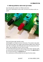
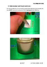
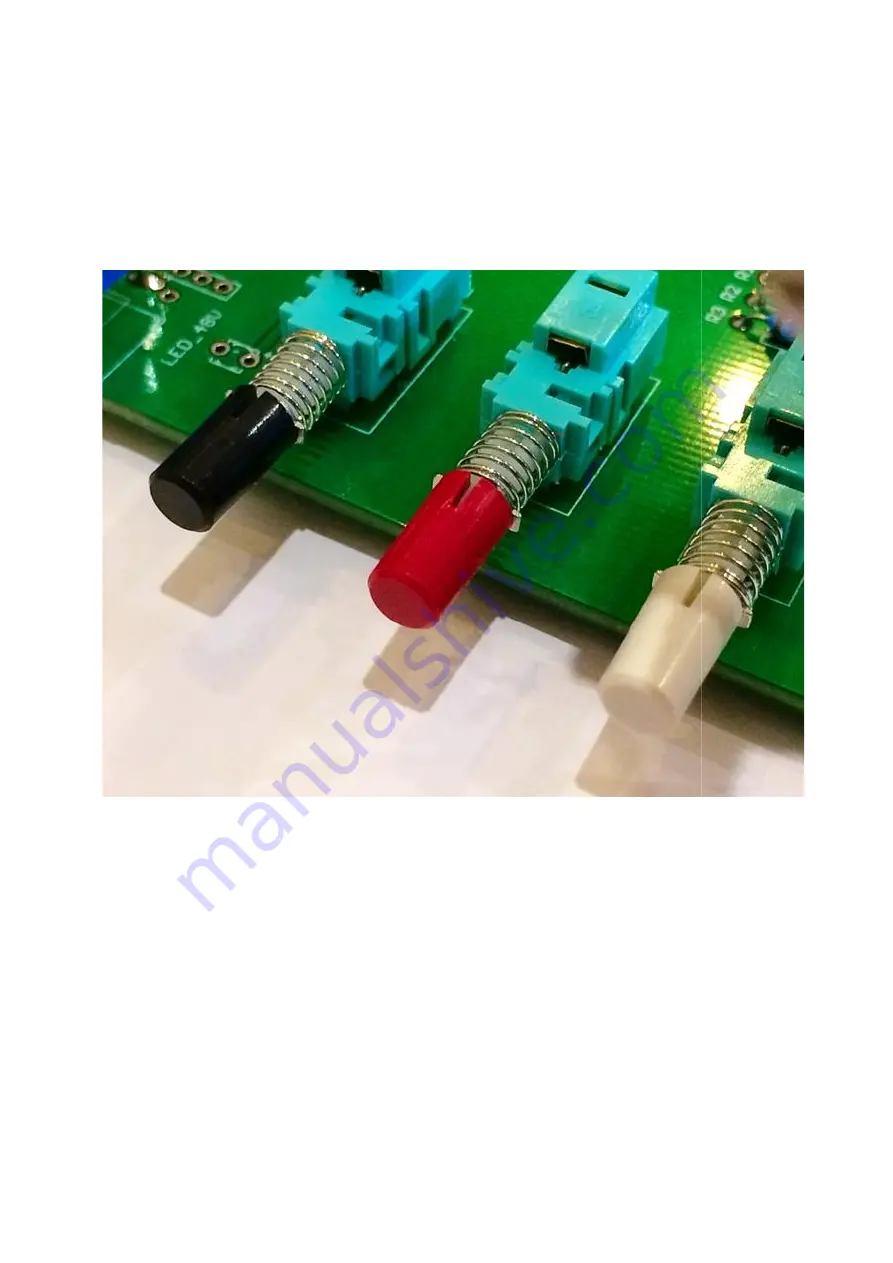
Insert all pushbutton switches into PCB and solder them
Then put on colored cups on each of them.
prefer!
Picture 5.
Next step: Soldering gain (variable) resistor.
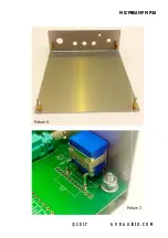
Install standoffs on L-bracket
the main PCB into place. Gain resistor must
point. After installing the main PCB, tighten all screws with spring washers. Gain
resistor must be installed in the hole on the L
We recommend soldering only the last two legs of Gain resistor. For best results
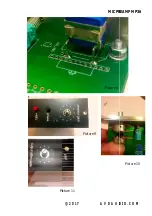
we recommend to install the face plate with T
11
. You can see this step in the
Then carefully remove PCB and solder all other pins of the Gain resistor
MIC PREAMP MP36
©
2017 AVDAUDIO.COM
Soldering pushbutton switches and gain resistor
Insert all pushbutton switches into PCB and solder them.
Then put on colored cups on each of them. Use colors in whichever order you
Next step: Soldering gain (variable) resistor.
bracket as shown in the picture. This is done to help install
the main PCB into place. Gain resistor must already be installed on the PCB at this
fter installing the main PCB, tighten all screws with spring washers. Gain
resistor must be installed in the hole on the L-bracket.
We recommend soldering only the last two legs of Gain resistor. For best results
we recommend to install the face plate with T-Pad resistor! See
picture 9,10
in the
picture 8
bellow.
Then carefully remove PCB and solder all other pins of the Gain resistor
MIC PREAMP MP36
AVDAUDIO.COM
n whichever order you
as shown in the picture. This is done to help install
be installed on the PCB at this
fter installing the main PCB, tighten all screws with spring washers. Gain
We recommend soldering only the last two legs of Gain resistor. For best results
picture 9,10
and
Then carefully remove PCB and solder all other pins of the Gain resistor.


