


BS; Reviewed:
SPOC 2/14/2005
Solution & Interoperability Test Lab Application Notes
©2005 Avaya Inc. All Rights Reserved.
14 of 22
RAD-IP-Mux.doc
4. Configure Avaya Communication Manager
Avaya Communication Manager can be configured via a System Access Terminal (SAT). There are
two basic configuration steps that need to be followed when the DS1 Remote Port Connectivity
application is deployed:
1. Configure Fiber link - The DS1 Converter Complex is installed in place of the
conventional fiber. The configurartion of the DS1 Converter complex is done by
configuring the conventional fiber link, administering the DS1 Converter related
parameters.
2. Synchronization – Configure and verify that the main PN and remote PN derive
synchronization from a common source.
4.1. Configure Fiber Link
Before configuring Avaya Communication Manager for DS1 remote Port Network connectivity,
make sure that the relevant hardware is installed as follows:
On main PN,
•
Switch Node Interface TN573B board, (e.g., in carrier slot
1E20
).
•
DS1 Converter TN1654 board, (e.g., in carrier slot
1E21
).
•
Connect TN573B and TN1654 with a TN1654 Y cable.
On remote PN,
•
Expansion Interface TN570B board, (e.g., in carrier slot
11A01
).
•
DS1 Converter TN1654 board, (e.g., in carrier slot
11A02
).
•
Connect TN570B and TN1654 with a TN1654 Y cable.
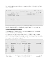
4.1.1. Configure the T1 Facility
Each DS1 Converter TN1654 board supports up to 4 T1 facilities, named as DS1C facility A, B, C
and D respectively. Set the dipswitches on the board for T1 operation for all the DS1C facilities.
The fiber-link administration in Avaya Communication Manager is used for configuring the DS1C
connection between the main PN and the remote PN. Consider the main PN and the remote PN as
the two endpoints connected via a “fiber link”. From the System Access Terminal (SAT), administer
a fiber link using the
add fiber-link x,
where x is the fiber link number. Configure the location of
the boards on each Endpoint that will be connected to form a fiber link, and the parameters
associated with each T1 facility.
The following example adds fiber-link number
11
to connect the main PN (Endpoint 1) to remote
PN (Endpoint 2):