

COMMUNICATION
Avaya 9130 1000–3000 VA UPS Site Preparation, Installation and Operator’s Manual
S
164201765 Rev 1
55
W A R N I N G
The relay output contacts must not be connected to any utility connected circuits. Reinforced
insulation to the utility is required. The relay output contacts have a maximum rating of
30 Vac/1A and 60 Vdc/2A nominal values.
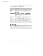
Table 5 shows the options for the relay output contacts.
Table 5. Relay Output Configuration Options
Signal
Description
UPS ok
Activated when the UPS is feeding the load on inverter or on
bypass and no alarms are active
On Bypass
Activated when the UPS is NOT on bypass operation
On Battery
Activated when the UPS operates on battery and the “On
Battery Notice Delay” time has expired
Battery Low
Activated with the “Battery Low” alarm according to the
“Battery Low Alarm” setting
Ext. Charger On
Controls an optional external battery charger on and off
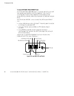
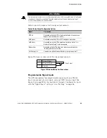
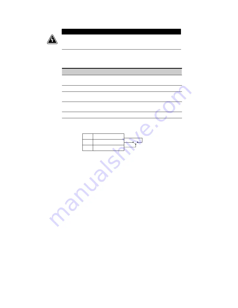
Figure 18 shows a schematic of the relay output contacts.
Common
Normally Closed
3
2
Normally Open
1
Relay Output
Figure 18. Standard Relay Port Connections
Programmable Signal Inputs
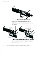
The UPS incorporates four programmable signal inputs: one RS-232
input, two connectivity card inputs, and one REPO terminal input. See
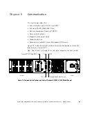
Figure 14 on page 49 for the locations of the ports. Configure the inputs
with the “Signal Inputs” setting in “User Settings” on page 36.