background image

12

CheckWheel


– This function checks whether the proper 

sequence of commands have been issued by the host 
to enable the wheel of the mouse. The sequence is three 
consecutive setting rate commands of 200, 100 and 80 
reports per second.

send_1


– sends a PS/2 1 bit

send_0


– sends a PS/2 0 bit

GetBit


– receives a PS/2 bit from the host

Interrupt Service Routines (ISR)

The CY7C63743-PXC features 12 different sources of 
interrupts. There are only four ISRs implemented in this 
application. If an interrupt is enabled and the conditions 
for the interrupts are met, the microcontroller will gener-
ate an interrupt. Upon servicing the interrupt, the hard-
ware will fi rst disable all interrupts by clearing the Global 
Interrupt Enable bit. This is followed by an automatic 
CALL instruction to the ROM address of the interrupt 
being serviced in the Interrupt Vector. The instruction in 
the Interrupt Vector is typically a JMP instruction to the 
Interrupt Service Routine (ISR). A RETI or RET instruction 
at the end of the ISR brings the program counter (PC) 
back to the location prior to the interrupt (POR and USB 
Bus Reset are exceptions).

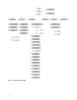
DualMain


– When power is fi rst applied to the CY7C63743-

PXC, a Power On Reset (POR) occurs; the microcontroller 
starts executing code from address 0x00. This is a JMP 
instruction to the 

DualMain 

routine. This routine initial-

izes the program stack pointer (PSP), data stack pointer 
(DSP), ram variables, and the GPIO pins. This routine calls 

GetMouseType 

which returns the interface of the mouse. 

If a USB interface is detected, the program jumps to 
the 

usbMain 

loop. Otherwise, the program goes to the 

ps2Main 

loop.

DualUsbBusReset_ps2Error


– The USB-PS2 Interrupt Mode bit 

in the USB Status and Control Register is defaulted to 
“0”, or USB mode. This indicates that the USB Bus Reset 
interrupt will be generated if the SE0 condition (D+ and 
D- are both LOW) exists for 256us. This ISR enables the 
USB Device Address, sets up the endpoint modes and 
jumps to 

usbMain 

for the USB initialization.

Dual1msTimer


– This ISR reads the current status of the 

buttons. Therefore, every one millisecond the button 
state is updated; the button status information will be 
used by the 

ProcessButtons 

function at a later time. This 

ISR maintains the 

dualInterface1ms 

counter variable 

which is used as a 1ms timing reference in other parts 
of the program. This routine also handles the entrance 
or exit from suspend. The mouse will prepare to enter 
a suspend (low power) state if there is no bus activity in 
3ms. If the mouse is confi gured for remote wakeup, the 
Bus Reset and wakeup interrupts are enabled prior to sus-
pending the chip. The program then enters a suspended 
state, and will wake at least as often as the wakeup timer 
interrupts or as a result of the USB Bus Reset interrupt. 
Each time the chip wakes up due to the wake up timer 
interrupt, the state of the buttons is examined by the 

GetButtons 

function. If a change in the button state has 

occurred, the mouse will generate a resume signal to 
the host and exit the ISR. If the device is not enabled 
for remote wakeup, only the USB bus reset interrupt is 
enabled, and the part is suspended. Only a Bus Reset can 
wake up the chip. If the resume was due to bus activity, 
the fi rmware returns to the main loop. If the resume was 
due to a button press, a K state is driven upstream for 14 
milliseconds prior to returning to the main loop. Moving 
the mouse will not wake the suspended system.

DualUsbEndpoint0_ps2Error


– This ISR is entered upon receiv-

ing an Endpoint 0 interrupt. Endpoint 0 interrupts occur 
during the Setup, data, and status phases of a control 
transfer. This ISR handler jumps to the proper routine to 
handle one of these phases.

DualUsbEndpoint1_ps2Error


– This ISR is entered upon re-

ceiving an Endpoint 1 interrupt. If the ACK bit is set, 
indicating that a mouse packet was just transmitted 
to the host successfully, the SIE automatically sets the 
endpoint mode to NAK_IN mode, and the data toggle 
bit is fl ipped for the next transaction. The data toggle bit 
should never be toggled if the interrupt was a result of a 
NAK transaction.

Содержание ADNK-3083

Страница 1: ...load a full array of pixel values from a single frame To learn more about sensor s technical information please visit the Avago web site at http www semiconductor Avago com Introduction This design gu...

Страница 2: ...D and Optical Encoder combination Mouse Buttons Mouse buttons are connected as standard switches These switches are pulled up by the pull up resistors inside the microcontroller When the user presses...

Страница 3: ...0 asm listing The following statements are the pin definitions as they exist today The firmware will use these definitions to read and configure the GPIO pins without any other modifications Communica...

Страница 4: ...in Figure 3 below ADNK 3083 Designer s Kit Optical Mouse The ADNK 3083 optical mouse unit allows users to evaluate the performance of the Avago s Optical Tracking Engine sensor lens LED assembly clip...

Страница 5: ...r IGES drawing Sensor Lens Object Surface 2 40 0 094 To Disassemble the ADNK 3083 Unit The ADNK 3083 comprises of the plastic mouse casing printed circuit board PCB lens buttons and USB cable See Figu...

Страница 6: ...lopment Kit and the CY3654 P05 Personality Board Programming support and programmer adaptors for the Cypress CY7C63743 PXC can be found through Cypress CY3649 xxxV CY3083 SC28 CY3083 08 or through mos...

Страница 7: ...c product Note 3 MaxPower value should be changed as per specific circuit s current draw 4 Post Enumeration Operation Once communication between the host and mouse is established the mouse now has the...

Страница 8: ...D sampled high disable the USB connect resistor and Delay 100 S If D and D are both 0 detect a USB interface else detect a PS2 interface SPIInit This routine is called in the try_download to enable t...

Страница 9: ...ep0InReceived This routine is entered whenever an IN packet is received on endpoint 0 ep0OutReceived This routine is entered whenever an OUT packet is received on endpoint 0 setDeviceConfiguration Thi...

Страница 10: ...l Map DualMain GetMouseType USB Main PS2 Interface System Initialization USB Initialization USBTaskLoop ProcessButtons ProcessOptics ReadMotionReg ReadDeltaX ReadDeltaY Read ZWheel Load new mouse pack...

Страница 11: ...mand from the host The PS 2 mode is then set to remote mode PS2SetWrapMode This routine is called in response to a SET WRAP MODE command from the host It then sets the mouse mode to wrap mode See the...

Страница 12: ...es and jumps to usbMain for the USB initialization Dual1msTimer This ISR reads the current status of the buttons Therefore every one millisecond the button state is updated the button status informati...

Страница 13: ...sePacket HostRequestToSend PS2Receive GetBit send0 ReadMotionReg PS2SendResponseByte PS2Send Send_1 Send_0 ResetInterval PS2SetScaling SetWrapMode SetDefault PS2StatusRequest SetRemoteMode CheckWheel...

Страница 14: ...ons L M QA QB Vcc GND V DD 19 16 GND 1K REFB 14 P0 3 7 NPD 4 P0 7 3 SCLK 21 P0 6 2 MISO 22 9 GUARD NC NC 11 18 20 P1 1 R 20 K 20 K 1 NCS LP2950ACZ 3 3 3 1 2 Vo Vin GND 4 7 F 0 1 F 0 1 F MMBT2222A 13 R...

Страница 15: ...S 1 R16 Chip resistor 20K 1 0805_CUS 2 R8 R10 Chip resistor 240R 1 0805_CUS 1 R4 Resonator 24MHz XTAL4 1 X1 Transistor 2N2222 TO92C 1 Q3 Ceramic cap 2 2uF 16V 1206 1 C5 Tant cap 4 7uF 16V 1206 2 C2 C4...

Страница 16: ...16 Figure C1 PCB Schematic Bottom Layer Figure C2 PCB Schematic Top Overlay Appendix C PCB Layout HLMP EG3E Figure C3 PCB Schematic Bottom Overlay...

Страница 17: ...tional view of PCB assembly highlighting all optical mouse components optical mouse sensor clip lens LED PCB and base plate Clip LED PCB Sensor Lens Light Pipe Surface Base Plate Appendix D Base Plate...

Страница 18: ...e Command Action 0xFF Reset Resets mouse to default states 0xFE Resend Resends last data to host 0xF6 Set Default Sets mouse to use default parameters 0xF5 Disable Disables the mouse 0xF4 Enable Enabl...

Страница 19: ...dicate that this is a Microsoft compatible three button wheel mouse the wheel report format is enabled After this initialization sequence the PS 2 wheel reporting format is enabled The fourth byte rep...

Страница 20: ...ADNS 2220 001 Assembly Clip Data Sheet d HLMP EG3E xxxxx Red LED Data Sheet Hardware Support Files a ADNK 3083 BOM List b ADNK 3083 Schematic c 3D Model IGES Files d Gerber File Software Support Files...

Отзывы: