


30
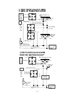
C. Locate the key in sensor switch wire that connects the chime module
to the ignition cylinder.
D. Cut this wire and connect the ignition cylinder side to terminal 30 of a
P&B VF45F11 or equivalent relay.
E. Connect the cathode (striped) side of a 4003 series diode to this
same wire, and connect the (non striped) side to the negative safely
input wire (WHITE/ BLACK) (H7/1) of the Remote Start Unit.
F. Connect terminal 86 of the relay to a fused + 12 volt constant battery
source.
G. Connect terminal 87 of the relay to the Chime Module side of the
previously cut wire in step D.
H. Connect terminal 85 of the relay to the Drivers Door side of the pin
switch wire previously cut in step B.
Note:
A second 4003 series diode may be required to maintain the
integrity of the hood open, shut down circuit. If this is the case, it
must be installed as shown in the diagram above. The anode (Non
Striped) side must be connected to the WHITE/ BLACK wire (H7/1)
of the Remote Start Unit. The cathode (Striped) side must be
connected to the hood pin switch.
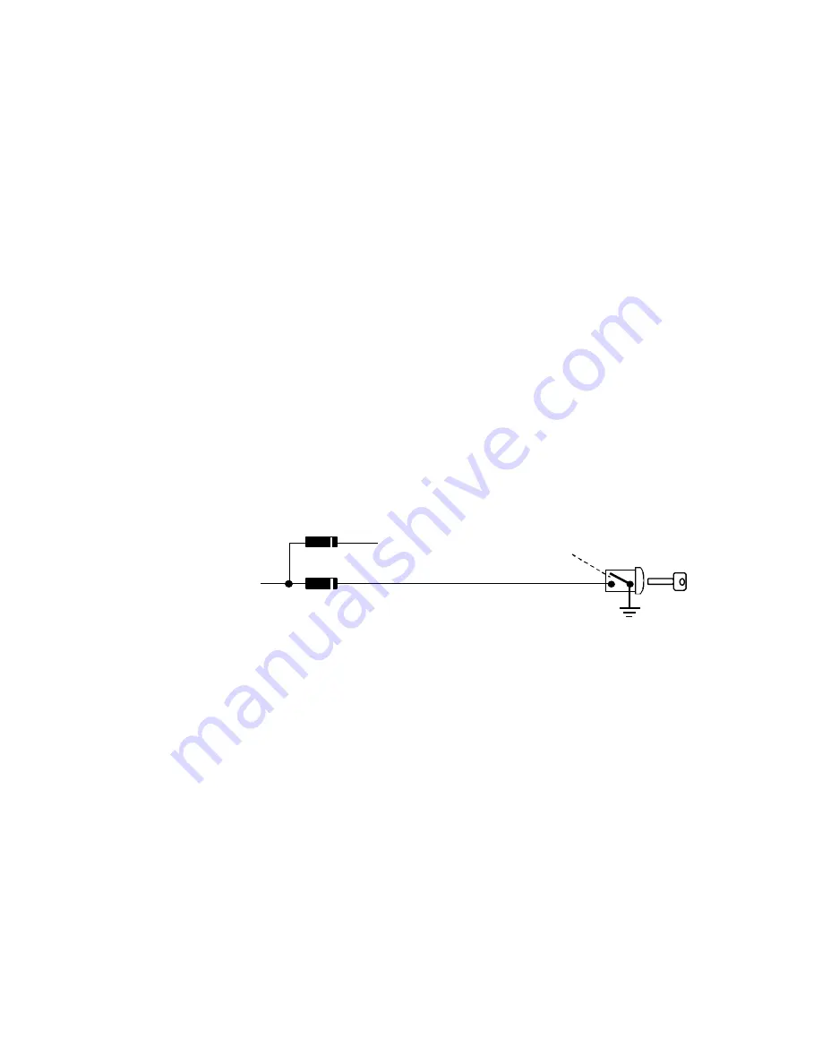
METHOD 2
Ignition Key In Sensor
Switch Closes with Key
In Ignition Cylinder
Switch
Connected to (
-
) Negative
Safety Input Wire
White/ Black
(
H7/1
)
To Hood Pin Switch
Safety Shut Down (
H7/1
)
1N4003
To connect to the key in sensor circuit as shown for method 2:
A. Locate the control wire that connects the drivers door pin switch to
the key in sensor switch.
B. Cut this wire and connect the ignition cylinder side to chassis ground.
C. Locate the key in sensor switch wire that connects the chime module
to the ignition cylinder.
D. Cut this wire and connect the ignition cylinder side to the Remote
Start Negative Safety Shut down wire WHITE/ BLACK (H7/1), using a
4003 series diode as shown above.
Note:
A second 4003 series diode may be required to maintain the
integrity of the hood open, shut down circuit. If this is the case, it must
be installed as shown in the diagram above. The anode (Non Striped)
side must be connected to the WHITE/ BLACK wire (H7/1) of the Remote
Start Unit. The cathode (Striped) side must be connected to the hood pin
switch.
AFTER THE CONNECTION OF THE NEUTRAL START SAFETY WIRE


