


15
WHITE/BLACK WIRE –
NEGATIVE SAFETY SHUT DOWN INPUT —
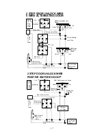
The WHITE/BLACK wire provides an instant shutdown for the remote
start, whenever it is grounded. Connect the wire to the hood pin switch
previously installed. This wire must be routed though a grommet in the
firewall and connected to the hood pin switch.
Important!
This connection is a safety wire and must be connected
as shown and tested as specified. Failure to do so may result in
personal injury or property damage. See detail of wiring in the
following diagram. This wire may also be used if the vehicle brake
light circuit switches ground to the brake lights. An isolation diode
must be used for ground switched brake light circuits and must be
connected to the output of the brake switch.
WHITE/RED wire—Tachometer Signal connection—
This input provides the remote start system with information about the
engine’s revolutions per minute (RPM). It can be connected to the
negative side of the coil in vehicle with conventional coils. In multi-coil
and high energy ignition system locating a proper signal may be more
difficult. Once connected, you must Program the Start Feature
D – 2
to
“Tachometer checking type” and teach the system the RPM signal.
(See Start Feature
D – 2 / 3
Programming.)
To test for a tachometer wire, a multi-meter capable of test AC voltage
must be used. The tachometer wire will show between 1V and 6V AC
at idle, and will increase as engine RPM increases. In multi-coil ignition
system, the system can learn individual coil wire. Individual coil wires in
a multi-coil ignition system will register lower amounts of AC voltage.
Also, if necessary, the system can use a fuel injector control wire for
engine speed sensing. Common locations for a tachometer wire are
the ignition coils itself, the back of the gauges, engine computers, and
automatic transmission computers.
IMPORTANT! Do not test tachometer wires with a test light or logic
probe. The vehicle will be damaged.
How to find a tachometer wire with your multi-meter
1. Set the ACV or AC voltage (12V or 20V is fine.)
2. Attach the (-) probe of the meter to chassis ground.
3. Start and run the vehicle.
4. Probe the wire you suspect of being the tachometer wire with the red
probe of the meter.
5. If this is the correct wire the meter will read between 1V and 6V.
NOTE:
No connection of this wire is required, if you use the voltage or
Timer-checking type mode.


