-|Transparent Guide|-
Configuration of ADIO-PN
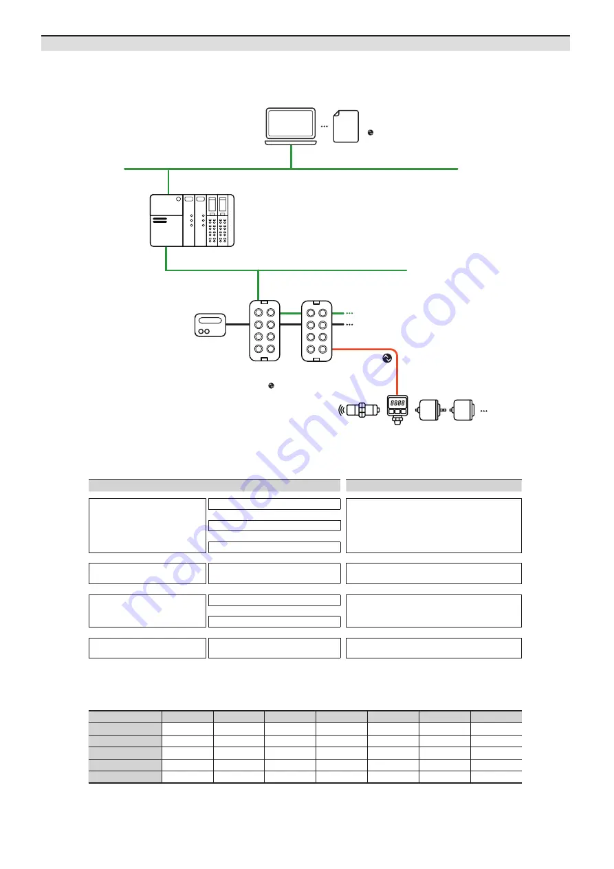
The figure below shows the PROFINET network and the devices that compose it.
For proper use of the product, refer to the manuals and be sure to follow the safety considerations in the manuals.
Download the manuals from the Autonics website.
STEP
Reference manual
Hardware installation
Install and ground the ADIO
ADIO-PN Product Manual
⬇
Connect the ports of ADIO
⬇
Supply power to the ADIO
⬇
IO-Link device settings
Set parameters and functions
of IO-Link device
atIOLink User Manual
⬇
PROFINET Master
↕
ADIO-PN
Integrate the ADIO-PN to PROFINET project
ADIO-PN (TIA Portal V16
Guide)
01)
⬇
Set the ports of ADIO-PN
⬇
Checking the operation
Check the indicators
ADIO-PN Product Manual
01) The project planning software of the upper level communication system may be different depending on the user’s environment.
For more information, refer to the manufacturer’s manual.
Operation mode
Safe State
01)
Validation
Data Storage
Input Filter
01)
Vendor ID
Device ID
Cycle Time
Digital Input
-
-
-
○
-
-
-
Digital Output
○
-
-
-
-
-
-
IO-Link Input
-
○
○
-
○
○
○
IO-Link Output
-
○
○
-
○
○
○
IO-Link Input/Output
-
○
○
-
○
○
○
01) Unsupported on the atIOLink
■
The supported parameters
Project planning software + GSDML file
at IODD file
PROFINET Master
ADIO-PN
: PROFINET Slave,
IO-Link Master
Power supply
IO-Link device
Ethernet / Fieldbus


