35
SC 600 II
Installation of Rack
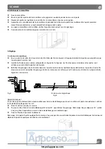
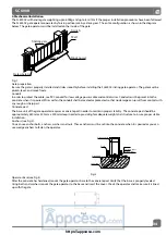
Fix the rack.
Lay the first piece of rack on the gear and weld the first nut on the gate.
Move the gate manually, checking if the rack is resting on the gear.
Bring another rack element near to the previous one. Move the gate manually as the first rack, thus proceeding until the gate is
fully covered.
When the rack has been installed, to ensure it meshes correctly with the gear.
The space between rack and gear is about 0.5mm.
Fig.4
5. Adjustment
Magnetic limit switch
To ensure safety, it is recommended to install limit switches at both ends of the gate to prevent the gate from sliding out of the
rails. The rails must be installed horizontally.
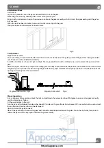
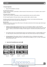
Install the limit block as shown in Fig.5 and Fig.6. The magnetic of limit switch and blocks are used to control the position of the
gate.
Release the gear with the key and push the sliding gate manually to pre-determine the position, fix the block to the rack and lock
the gear by push up the release bar. Moving the gate electrically, adjust the block to the proper position until the position of the
opening and closing meet the requirement.
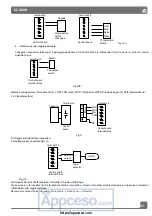
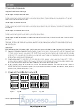
Gear
Sliding gate
Rack
Limit block
Magnetic
Magnetic limit switch Fig.5
Magnetic limit switch Fig.6
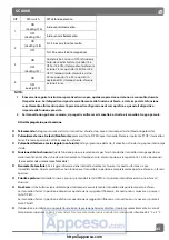
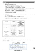
Manual operation
In case of power failure use key unlock the lock and pull down the release bar about 90 degree to open or close gate manually,
use the release key as follow:
Fit the supplied key in the lock.
Turn the key and pull down the release bar about 90°to release the gear. (Note: Do not exceed 90°, be careful not to use too much
force, otherwise the release bar will be damaged.)
Open and close the gate manually.
Note: If the gate bumps the mounting post and cannot be electric opened, move the gate a few inches by hand, thus you can
release the gate with the key, open and close the gate manually.
Fig. 7
https://appceso.com
Содержание SC 600 II Series
Страница 42: ...41 SC 600 II https appceso com ...
Страница 43: ...42 SC 600 II https appceso com ...
Страница 44: ...https appceso com ...

