


Page 4
DURA
pulse
GS20 AC Drive Quick-Start Guide – 1st Ed, Rev C 03/03/2022
DURA
pulse
GS20 AC Drive Quick-Start Guide
GS20_QSP 1st Edition, Rev C 03/03/2022
Introduction – How To Get Started
Automationdirect.com would like to thank you for your purchase of the Durapulse GS20 AC drive. The GS20
drive is a state-of-the-art, full-featured AC drive. The Quick-Start Guide below will introduce you to many of
the GS20 drive features and help you configure the GS20 drive in a minimum amount of time.
STO (Safe Torque Off) / Emergency Stop
The GS20 drive offers Safe Torque Off (STO) functionality, instead of a standard Emergency Stop circuit. STO
provides the ability to immediately turn off the output of the GS20 drive in the event of an emergency, without
the need for an emergency stop contactor between the drive and motor.
Please see the Control-Circuit Wiring diagrams (
) for how to wire the STO circuit. From the factory,
the GS20 STO terminals are jumpered and the STO circuitry of the drive is bypassed. STO is recommended for
personnel safety.
After wiring the drive (
but before applying power
), the first thing you should do is press the E-stop button (or
otherwise break the safety circuit) and verify that the circuit between the STO1/STO2 terminals and the STO
+24V terminal is not connected. If these circuits are open, the STO feature will stop all power from going to the
motor and there will be no danger of unexpected movement when you power up the drive.
Powering Up the GS20 Drive
Apply AC line power to the GS20 drive, but don’t engage the safety circuit yet (keep the E-stop PB pushed in).
Starting, Stopping, and Controlling the Speed of the GS20 Drive
Out of the box GS20 drives are set to use the keypad buttons to RUN and STOP the drive and vary the drive
speed. The drive can also be configured to run from potentiometers, external pushbuttons, Ethernet
communication, etc.
Do not attempt to run the motor yet. Certain parameters (especially the motor protection parameters) must
be set first.
Configure the Drive
The tables below list those parameters typically used in most applications. You can navigate to any of these
parameters through the keypad. (Refer to
for information and instructions for using the Digital
Keypad.)
All applications need to configure the parameters in the “Quick Configuration” table. At minimum, you MUST
configure these motor parameters before operating the drive:
• 01.02 Motor1 Max Output Voltage (this will typically be either 230V or 460V)
• 05.01 Motor1 Rated Amps (depends on the motor)
• 01.01 Motor1 Max Output Frequency (this will typically be 50Hz or 60Hz)
The main configuration parameters required to get your drive up and running are included in this guide.
For more advanced configuration options, please see the User Manual. Your application will dictate which
parameters need to be configured. It is NOT necessary to configure every parameter listed in the tables in the
User Manual, use only those you need.
Parameter Groups
Group Number
Group Category
00
Drive Config
01
Basic Config
02
Digital I/O Config
03
Analog I/O Config
04
Multi-Step Speed Config
05
Motor Config
06
Protection Config
07
Special Parameters
08
PID Config
09
Communications Config
10
Speed Control Config
11
Advanced Config
13
Macro Config
14
Protection (2) Config
After configuring the minimum settings, you can now engage the safety circuit. The RUN and STOP/RESET
buttons should Start and Stop the drive. To adjust the output frequency, press the MENU button repeatedly
until the “F xx” appears for “Frequency Setpoint”. Use the Up and Down arrow buttons to adjust the frequency,
then press ENTER to confirm. Press ENTER again to return to the main menu.
Parameter Set Up
DURA
pulse
GS20 AC Drives offer parameter setup from the keypad for some of the most common drives
applications. Choose parameters from the table below, then set the applicable parameters for that
application as shown.
To Configure Parameters:
From the power up screen:
1) Press
MENU
until you see
H 0.00
(this is the actual drive frequency) and press
ENTER
.
2) Use the
UP/DWN
arrows to select the parameter group you want and press
ENTER
.
3) Use the
UP/DWN
arrows to select the parameter number you want within that group and press
ENTER
.
4) Change the value of the parameter using the
UP/DWN
arrows and press
ENTER
.
5) Press
MENU
to exit back to the main menu.
6) Repeat as needed until all required parameters are configured.
Please refer to the user manual if you need more detailed information about the
parameters.
DURA
pulse
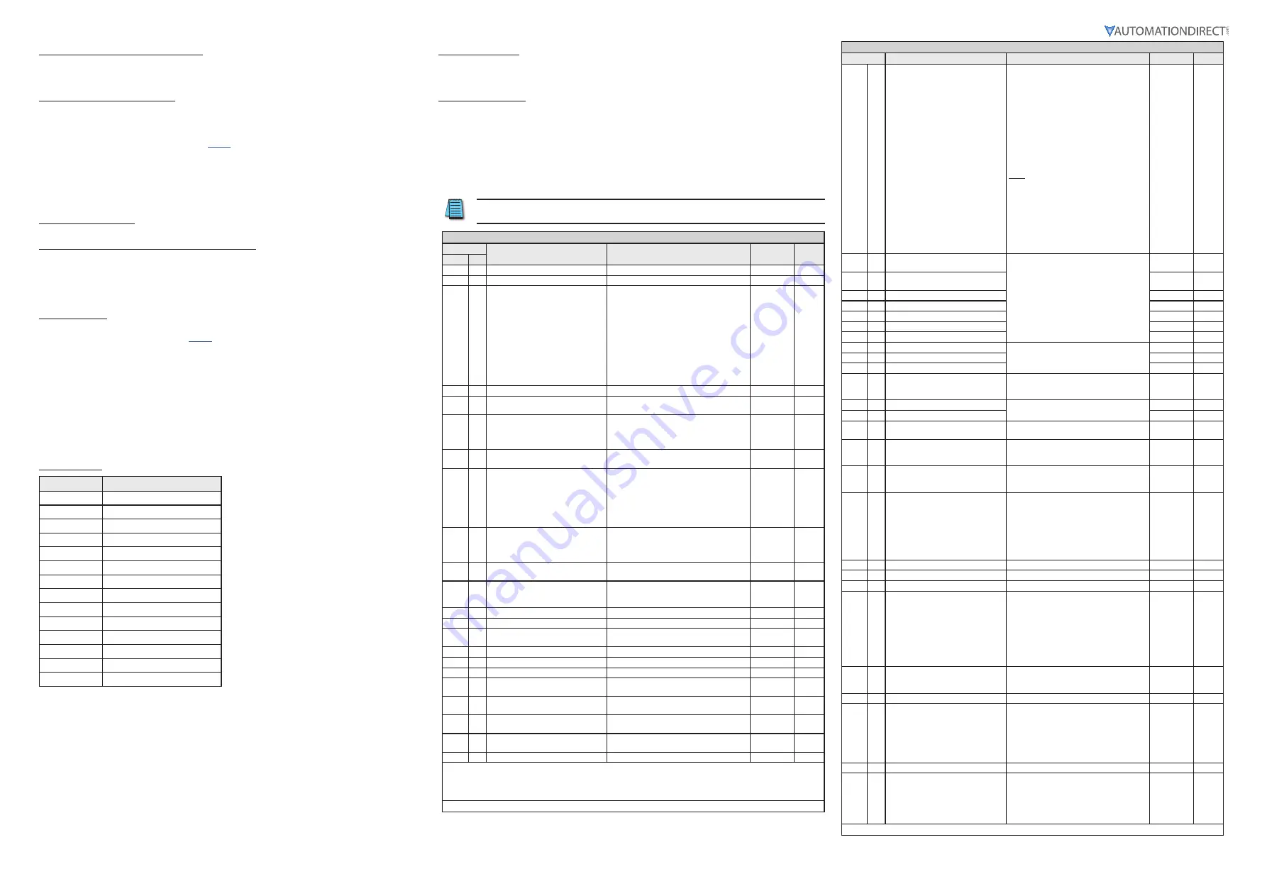
GS20 Parameter Settings – Quick Configuration*
Parameter
Description
Range
Default
User
Group
#
00 00
GS20 Model ID
Read Only
n/a
00 01
Displays AC drive rated current
Displays value based on model
n/a
00 02
Restore to default**
0=No function
1=Parameter write protect
2=Reset to GS2 mode (1 of 2)
5=Reset kWH display to 0
6=Reset PLC
7=Reserved
8=Keypad doesn’t respond
9=Reset 50Hz defaults
10=Reset 60Hz defaults
11=Reset 50Hz defaults (keep user config)
12=Reset 60Hz defaults (keep user config)
20=Reset to GS2 mode (2 of 2)
0
00 06
Firmware Version
Read Only
n/a
00 10
Control Mode
0=Speed mode
2=Torque mode
0
00 11
Speed Control Mode
0
=
VF (IM V/F control)
1=VFPG (IM V/F c Encoder)
2
=
SVC (Parameter 05.33 set as IM or PM)
5=FOC (Field Oriented Control)
0
00 16
Load Selection
0
=
VT
1
=
CT
1
00 20
Frequency Command Source (Auto)
0=Digital keypad
1=Communication RS-485 input
2=External analog input (refer to parm 03.00)
3=External UP/DOWN terminal
4=Pulse input without direction command
(refer to parm 10.16 without direction)
7=Digital keypad dial
0
00 21
Operation Command Source (Auto)
0=Digital keypad
1=External terminals
2=Communication RS-485 input
5=Communication card
0
00 22
Stop Method
0=Ramp to stop
1=Coast to stop
0
00 23
Motor Direction Control
0=Enable forward/reverse
1=Disable reverse
2=Disable forward
0
01 00
Motor 1 Max Frequency
0.00-599.00 Hz
60
01 01
Motor 1 Base Frequency
0.00-599.00 Hz
60
01 02
Motor 1 Rated Voltage
110V/230V: 0.0~255.0
460V: 0.0~510.0V
220.0
440.0
01 09
Startup Frequency
0.00-599.0 Hz
0.5
01 10
Output Frequency Upper Limit
0.00-599.0 Hz
599.0
01 11
Output Frequency Lower Limit
0.00-5.99.0 Hz
0.00
01 12
Acceleration Time 1
P01.45=0: 0.00-600.00 sec
P01.45=1: 0.00-6000.00 sec
10.00
10.00
01 13
Deceleration Time 1
P01.45=0: 0.00-600.00 sec
P01.45=1: 0.00-6000.00 sec
10.00
10.00
01 20
Jog Acceleration Time
P01.45=0: 0.00-600.00 sec
P01.45=1: 0.00-6000.00 sec
10.00
10.00
01 21
Jog Deceleration Time
P01.45=0: 0.00-600.00 sec
P01.45=1: 0.00-6000.00 sec
10.00
10.00
01 22
Jog Frequency
0.00-599.0 Hz
0.5
* Assumes default V/Hz mode with no feedback. To change control modes see complete parameter listing in User manual.
** Reboot drive after resetting defaults.
Note:
Drive default is Auto mode and cannot be changed from the keypad. For Local/Hand, use Discrete input configuration
settings (P02.00–P02.07) and P00.29–P00.31.
(table continued next column)
DURA
pulse
GS20 Parameter Settings – Quick Configuration (continued)
Parameter
Description
Settings
Default
User
02 00
2-wire / 3-wire Control
0=No function
1=2-wire mode 1, power on for operation
control (M1: FWD/STOP, M2: REV/STOP)
2=2-wire mode 2, power on for operation
control (M1: RUN/STOP, M2 REV/FWD)
3=3-wire, power on for operation control
(M1: RUN, M2: REV/FWD, M3: STOP)
4=2-wire mode 1, fast start up
(M1: FWD/STOP, M2: REV/STOP)
5=2-wire mode 2, fast start up
(M1: RUN/STOP, M2: REV/FWD)
6=3-wire, fast start up
(M1: RUN, M2: REV/FWD, M3: STOP)
Note:
In fast start up mode, the drive skips
detecting IGBT signal and will run
immediately. When using fast start up mode:
• Terminal output stays in ready status and
drive responds to commands immediately.
• The output terminal will have higher
voltage
• If the drive is short circuited an OC error
will display when running up
1
02 01
Multi-function Input Command 1
(FWD/DI1)
See “Multi-function Input Selections” on
0
02 02
Multi-function Input Command 2
(REV/DI2)
0
02 03
Multi-function Input Command 3 (DI3)
1
02 04
Multi-function Input Command 4 (DI4)
2
02 05
Multi-function Input Command 5 (DI5)
3
02 06
Multi-function Input Command 6 (DI6)
4
02 07
Multi-function Input Command 7 (DI7)
0
02 13
Multi-function Output 1 (R1)
See “Multi-function Output Selections” on
11
02 16
Multi-function Output 2 (DO1)
0
02 17
Multi-function Output 3 (DO2
0
02 35
Auto-run on Power-up (includes after
a Fault reset)
0: Disable
1: Drive Runs if Cmd ON after Flt Reset or
Pwr up
0
03 00
Analog Input Selection (AI1)
See “AI Multi-function Input Selections” on
1
03 01
Analog Input Selection (AI2)
0
03 20
Multi-function Output (AO1)
See “AO1 Multi-function Output Selections”
0
03 29
AI2 terminal input selection
0=4-20 mA
1=0-10 V
2=0-20 mA
0
04
00
to
14
Multi-step Speed Frequency 1–15
0.00-599.00 Hz
0.00
05 00
Motor Parameter Auto-tuning
0=No function
1=Dynamic test for induction motor (IM)
2=Static test for induction motor (IM)
5=Rolling auto-tuning for PM (IPM /SPM)
6=Simple rolling auto-tuning for induction
motor (IM)
12=FOC sensorless inertia estimation (IM)
13=High frequency stall test for PM
0
05 01
Motor 1 Full Load Amps (FLA)
10-120% of drive rated current
#.##
05 03
Motor 1 Rated RPM
0-65535
1710
05 04
Motor 1 Number of poles
2-20
4
06 06
Over-torque Detection Selection
(Motor 1)
0=No function
1=Continue operation after over-torque
detection during constant speed operation
2=Stop after over-torque detection during
constant speed operation
3=Continue operation after over-torque
detection during RUN
4=Stop after over-torque detection during
RUN
0
06 07
Over-torque Detection Level (Motor 1)
10–250%
(100% corresponds to the rated current of
the drive)
120
06 08
Over-torque Detection Time (Motor 1) 0.1–60.0 seconds
0.1
06 13
Motor 1 Electronic Thermal Overload
Relay
0=Inverter motor (with external forced
cooling)
1=Standard motor (motor with fan on the
shaft)
2=Disabled
Note:
A value of 1 or 2 is recommended to
protect the motor in most applications.
2
06 14
Motor 1 Electronic Thermal Relay Time 30.0-600.0
60
06 55
Drive Derating Method
0=Constant rated current and limit carrier
wave by load current and temperature
1=Constant carrier frequency and limit load
current by setting carrier wave
2=Constant rated current (same as setting 0)
but close current limit
0
(table continued next page)


